ACI Learning
by Vikas Srivastava
Opinions expressed are solely my own and do not express the views or opinions of my employer.
Revised Learning Path
- Finish “Your First Seven Days Of ACI” - BRKACI-1001
- Finish “Mastering ACI Forwarding Behaviour – A Day in the Life of a Packet - BRKACI-3545”
- Finish to ACI Bootcamp Videos
- Labs on Digital Learning
- Labs on AS CX
Write an overall learning summary and path here.
- Learning notes from BRKACI-3545 Ciscolive Session
- Read
https://www.cisco.com/c/en/us/solutions/collateral/data-center-virtualization/application-centric-infrastructure/white-paper-c11-739989.htmlEMEAR DCV PVT - ACI troubleshooting with TAC experts - LiveLessons Course
- INE Course
-
Look at the Youtube Video : VXLAN Part 6 - BGP EVPN Configuration on Nexus 9000 - Look at the videos here : https://www.youtube.com/watch?v=EHoAtPaW3oo
Learn VLXLAN which lays the foundations right
Reference Videos
BRKACI-2008 - A Technical Introduction into ACI
BRKACI-2004 - How to setup an ACI fabric from scratch
BRKACI-2102 - ACI Troubleshooting
BRKACI-2003 - Deployment Options for Interconnecting Multiple ACI Fabrics
BRKACI-3503 - Extending ACI to Multiple Sites - Dual Site Deployment Deep Dive
BRKACI-2020 - Understanding Cisco ACI Architecture and Scalable Layer-3 DCI / WAN integration with OPFLEX
BRKACI-2001 - Integration and Interoperation of Existing Nexus Networks into an ACI Architecture
BRKACI-2121 - Making the best of Services Automation with ACI Service Graph and Python
BRKSEC-3004 - Deep Dive on Cisco Security in ACI
Basic Packet Flow in an ACI
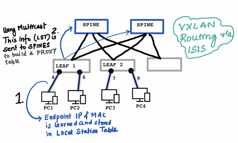
Local Station Table and Global Station Table are on Leaf Proxy Table is on the Spine
ON THE LEAF : In the local station table the IP address , MAC Address and port number is learned on the Leaf
The learning switch does not know the subnet mask of the learned the IP Address. (hence /32)
In a “normal” switch the “switching” happends based on the learnt MAC Address , in ACI it is a combination if Switching and Routing.
# Local Station LEAF-1

IP Address   MAC-Address    Port
-------------------------------------
10.1.1.1/32      MAC-PC1      Port-4
10.1.2.1/32      MAC-PC2      Port-6
# Local Station LEAF-2

IP Address   MAC-Address    Port
-------------------------------------
10.2.2.1/32      MAC-PC3      Port-7
10.1.2.6/32      MAC-PC4      Port-9
ON THE SPINE : The Leaf sends this information to the Spines using multicast , so that it can send it to multiple spines at the same time. The SPINEs build up a PROXY table which has informations on the IP Address and Corresponding VTEP.
Inter Fabric Routing setup is via ISIS Only , BGP is only used for L3 Out.
# Proxy Table for SPINE1 and SPINE2 contains everyones information

IP            VTEP1
10.1.1.1/32      192.168.1.1 (Leaf 1 VTEP)
10.1.2.1/32      192.168.1.1 (Leaf 1 VTEP)
10.2.2.1/32      192.168.1.2 (Leaf 2 VTEP)
10.1.2.6/32      192.168.1.2 (Leaf 2 VTEP)
SCENARIO 1 : When PC1:10.1.1.1 wants to talk to PC3:10.2.2.1:
ARP Process to Be Clarified and Documented later as this example is directly assuming that the IP Address is known
- A lookup is done in
Leaf1’s Local station table and is NOT found. - A look is done on the
SPINE’s proxy table , which responds back witht he VTEP address of the Leaf which has the IP Address10.2.2.1 Leaf1Stores this received information about10.2.2.1into itsGlobal Station Table- Communicatin starts on a VXLAN encapuslated packet as usual.
# Global Station Table on Leaf 1

IP            VTEP1
10.2.2.1     192.168.1.2 (Leaf 2 VTEP)
# Global Station Table on Leaf 2

IP            VTEP1
10.1.1.1     192.168.1.1 (Leaf 2 VTEP)
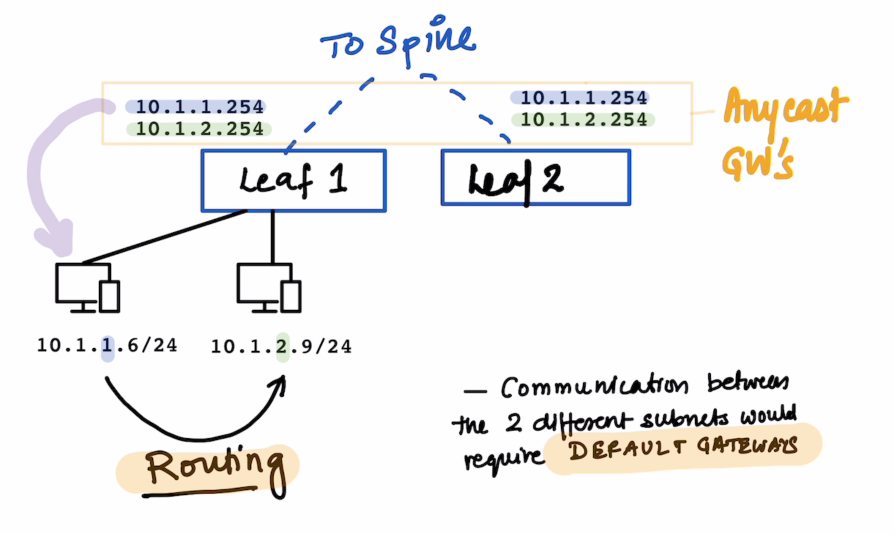
Since the two PCs above are in different Subnets , Routing would take place when they need to talk to each other.
The default gateways for the same are configured on the leafs.
10.1.1.25410.1.2.254
All these subnets are defined on the Bridge Domain Bridge Domain is your VXLAN
For communications for the devices on the same Leaf the Leaf responds to local ARP queries.
The VLANs in ACI are not significant within the ACI fabric ; The VLANs are still significant for backward compatibility with L2 Out Networks.
Endpoint
What is an endpoint ?
It’s a combination of MAC address and IP Address.
We can see it on the APIC
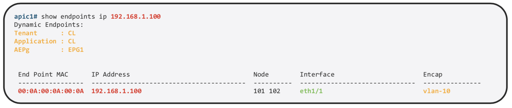
We can find more details about the same on the specific Leaf
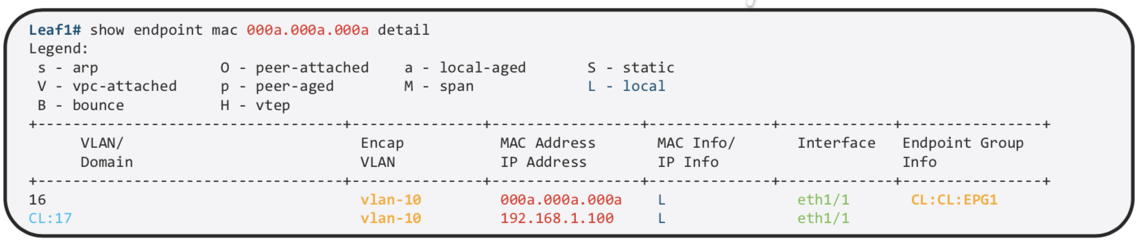
MAC and /32 IP Address are stored in the Endpoint Table
Exception is L3 Out , If we use the same mechanism of learnign all the IP Address , on the MAC address on Nexus router we would have thousand of /32. Other IP Information is used int he Ip Table just as the normal routing. That is the reason why we use arp table for L3 out.
Forwarding Table Lookup Order
- First : Endpoint Table (
show endpoint) - Second : RIB (
show ip route)
End Point Group
Endpoint Group is a logical grouping of hosts (EPs). Each EPG belongs to a bridge domain (BD)
EPG is used to implement the filtering with a contract.
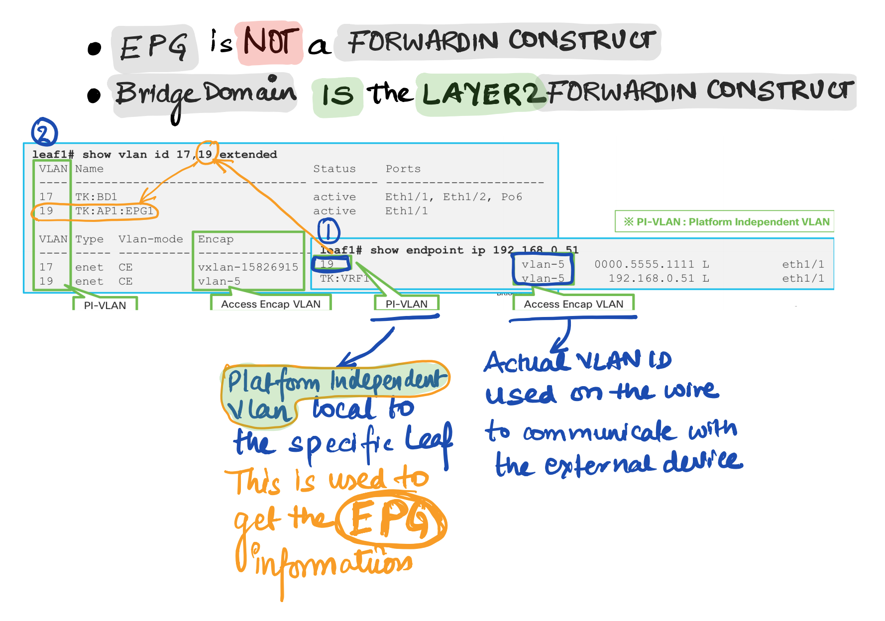
EPG is basically a security domain , but EPG is still using VLAN. So what is VLAN being used for. VLAN is just an identifier for the EPG
EPG is not a forwarding domain. Bridge Domain is the L2 Forwarding Domain If its L3 , its the VRF.
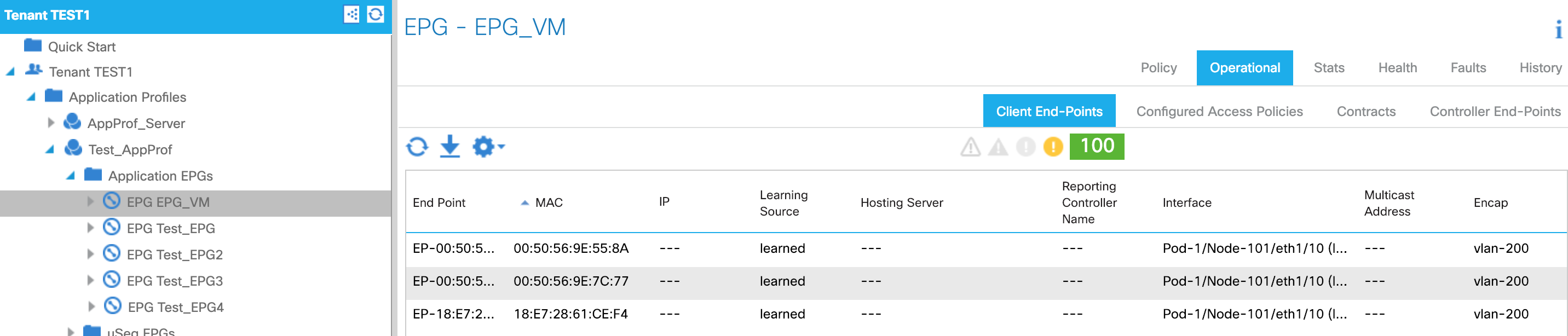
How to check endpoints
GUI
CLI
LEAF1# show endpoint ip 192.168.1.23
Legend:
 s - arp              O - peer-attached    a - local-aged       S - static
 V - vpc-attached     p - peer-aged        M - span             L - local
 B - bounce           H - vtep
+-----------------------------------+---------------+-----------------+--------------+-------------+
      VLAN/                           Encap           MAC Address       MAC Info/       Interface
      Domain                          VLAN            IP Address        IP Info
+-----------------------------------+---------------+-----------------+--------------+-------------+
16                                        vlan-3091    0050.5669.c00b L                        po19
DC1-HyperFlex-NSX:DC1-HyperFlex           vlan-3091      192.168.1.23 L                        po19


LEAF1# show vlan id 16,31 extended

 VLAN Name                             Status    Ports
 ---- -------------------------------- --------- -------------------------------
 16   DC1-HyperFlex-NSX:DC1-HyperFlex- active    Eth1/7, Eth1/21, Eth1/22,
      NSX-AP:DC1-HyperFlex-FI-ESX-               Eth1/40, Po3, Po19, Po21
      MGMT-VLAN-3091
 31   DC2-UCS-N5K-NSX:DC2-UCS-N5K-NSX- active    Eth1/21, Eth1/22, Po3
      AP:DC2-ISCSI-VLAN-1

 VLAN Type  Vlan-mode  Encap
 ---- ----- ---------- -------------------------------
 16   enet  CE         vlan-3091
 31   enet  CE         vlan-1
LEAF1#
VLAN types in ACI
Endpoint Type
PERVASIVE GATEWAY
What is pervasive GW for?
-
To be a default GW for EPs in the Fabric , All EPs can have consistent gateway IP address one hop away
-
To represent subnets (IP ranges) for a BD.
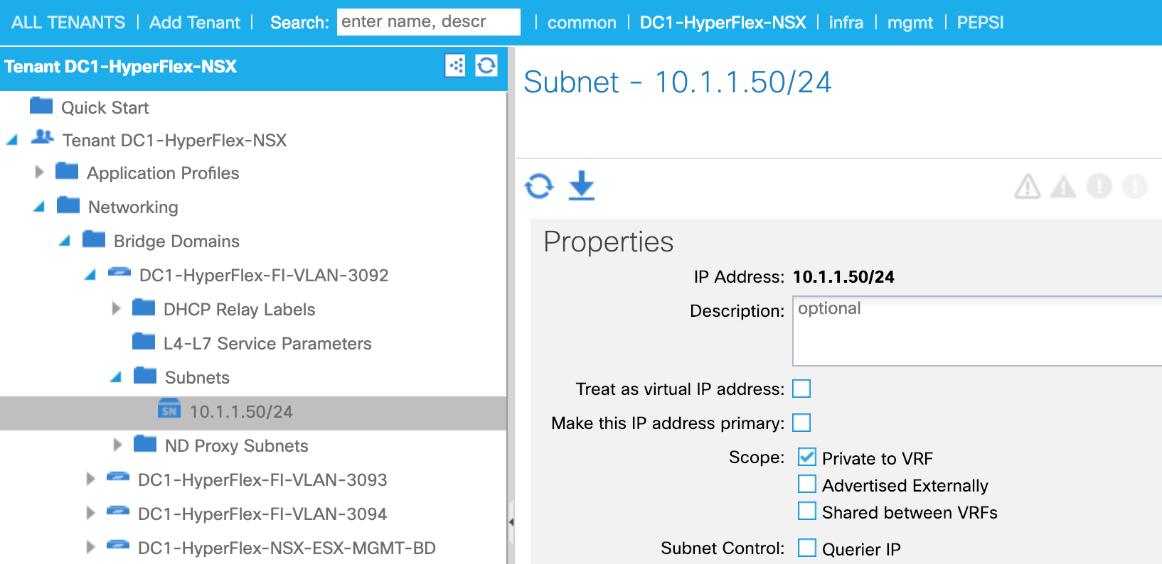
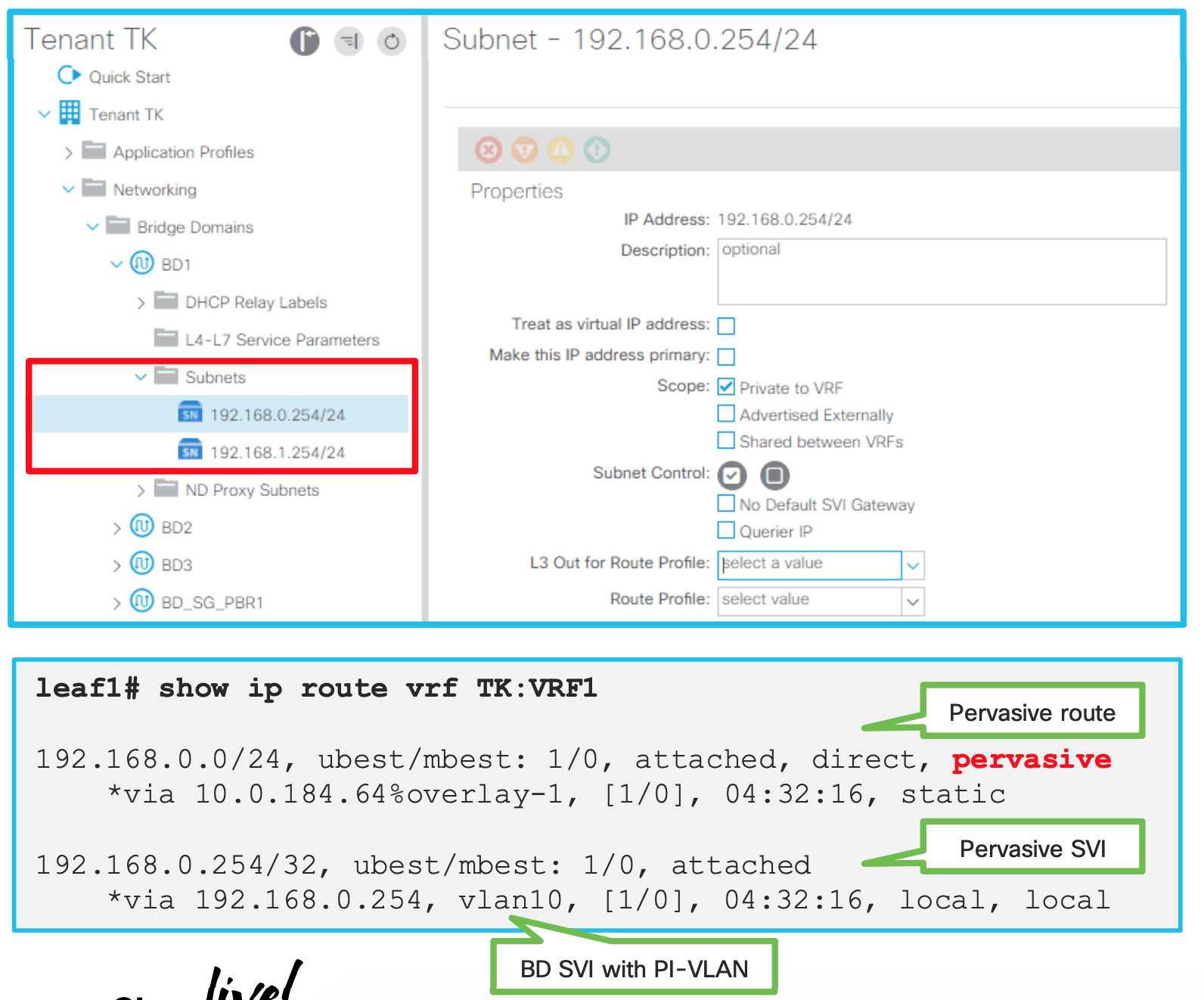
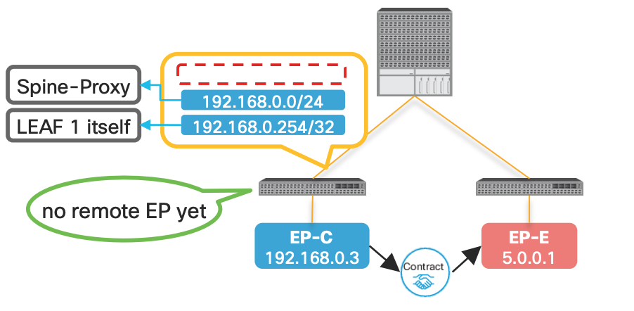
How is pervasive GW deployed? (When no contracts associated)
-
PI-VLAN for BD is used to represent a pervasive GW SVI
-
A pervasive SVI has secondary IP when multiple pervasive GWs are configured on the same BD
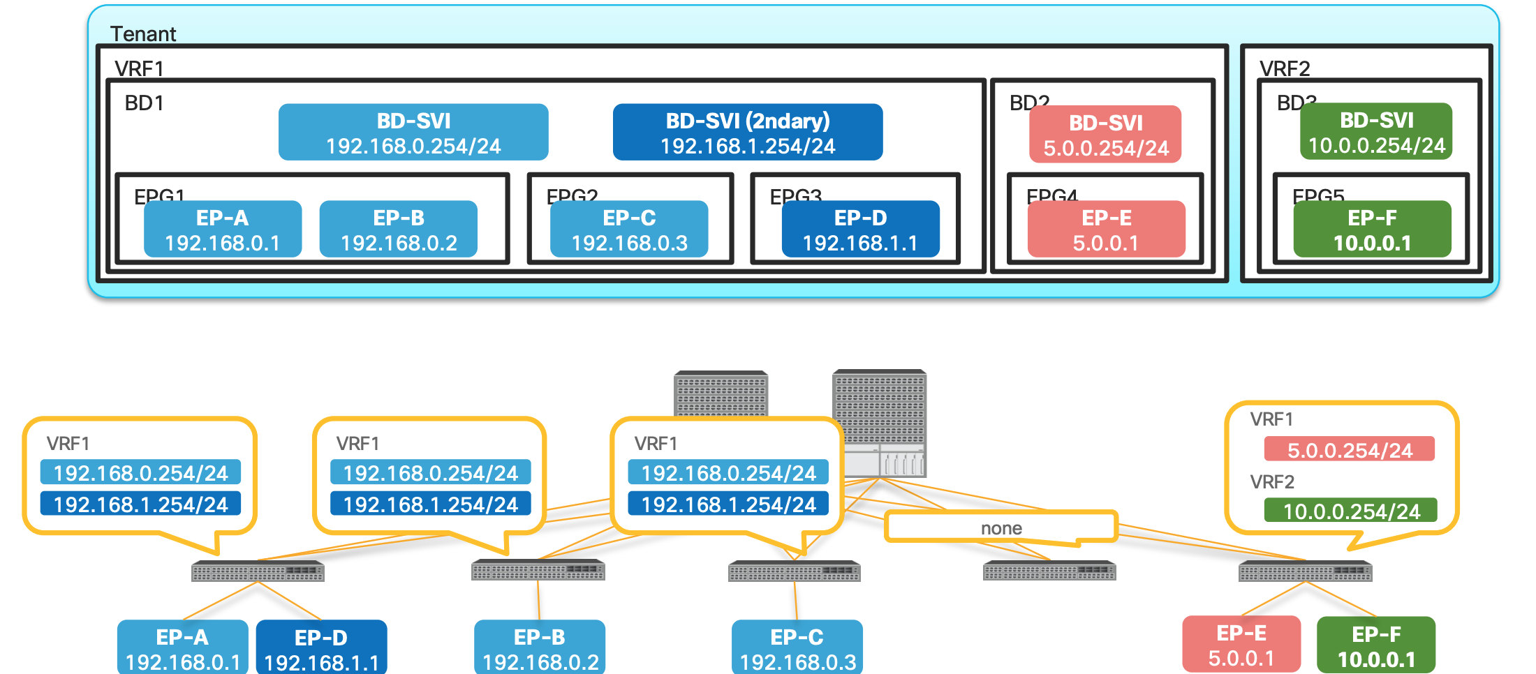
- In the above picture Bridge Domain has multiple EPGs in it.
- Both Primary and Secondary SVIs are installed on the switches which has EPGs or Endpoints assigned on those leafs.
- Leaf 4 does not have any EPs , hence no SVIs
- EP-E and EP-F are only on 5th Leaf hence the SVIs are only there.
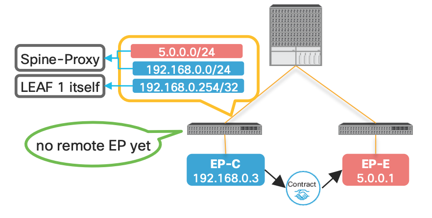
How is pervasive GW deployed? (When a contract is associated)
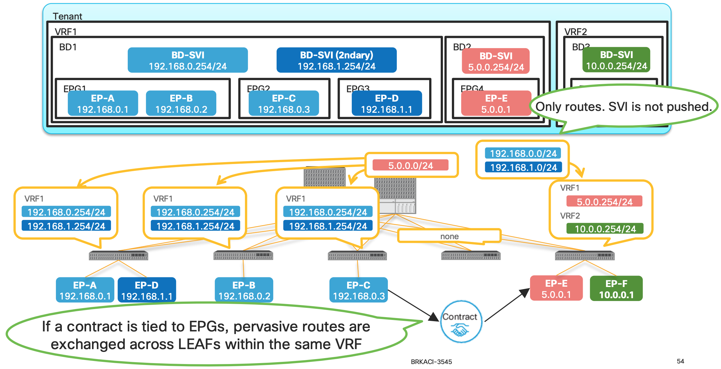
- When a contract is associated , the pervasive routes are exchanged.
- In the above example since the contract are between Endpoint-C and Endpoint-E the Pervasive routes of the Bridge Domain are exchanged between the BD1 and BD2.
- In this example , the pervasive route
5.0.0.254is shared to the BD1 and same from BD1 (192.168.0.254 and 192.168.1.254) is shared to the BD2.
Why are we doing the above exchange of routes ?
This is the key to understand how the ACI is doing Spine-Proxy Why does ACI push pervasive routes to other LEAFs after a contract? Pervasive routes are required for Spine-Proxy
Let’s understand it better :
What is a Spine Proxy
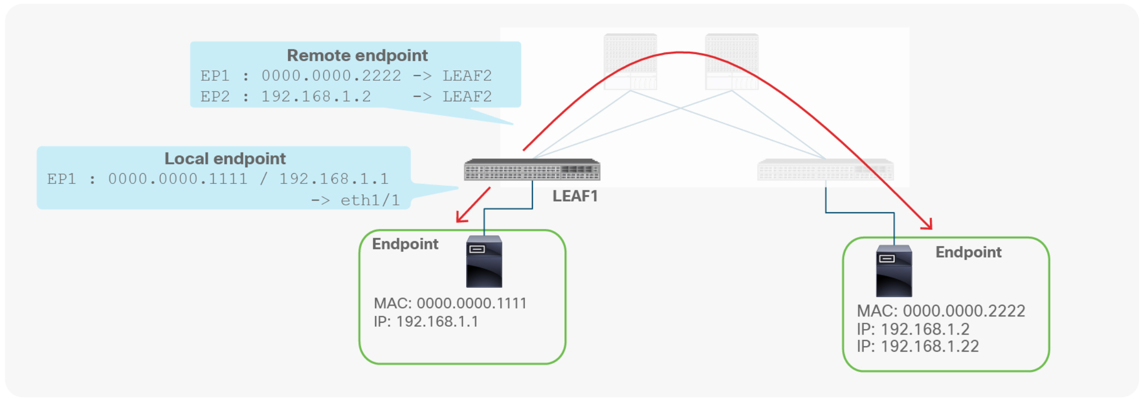
A leaf switch has two types of endpoints: local endpoints and remote endpoints. Local endpoints for LEAF1 reside directly on LEAF1 (For example, directly attached), whereas remote endpoints for LEAF1 reside on other leaf endpoints (picture above).
Although both local and remote endpoints are learned from the data plane, remote endpoints are merely a cache, local to each leaf. Local endpoints are the main source of endpoint information for the entire Cisco ACI fabric. Each leaf is responsible for reporting its local endpoints to the Council Of Oracle Protocol (COOP) database, located on each spine switch, which implies that all endpoint information in the Cisco ACI fabric is stored in the spine COOP database. Because this database is accessible, each leaf does not need to know about all the remote endpoints to forward packets to the remote leaf endpoints. Instead, a leaf can forward packets to spine switches, even if the leaf does not know about a particular remote endpoint. This forwarding behavior is called S P I N E - P R O X Y.
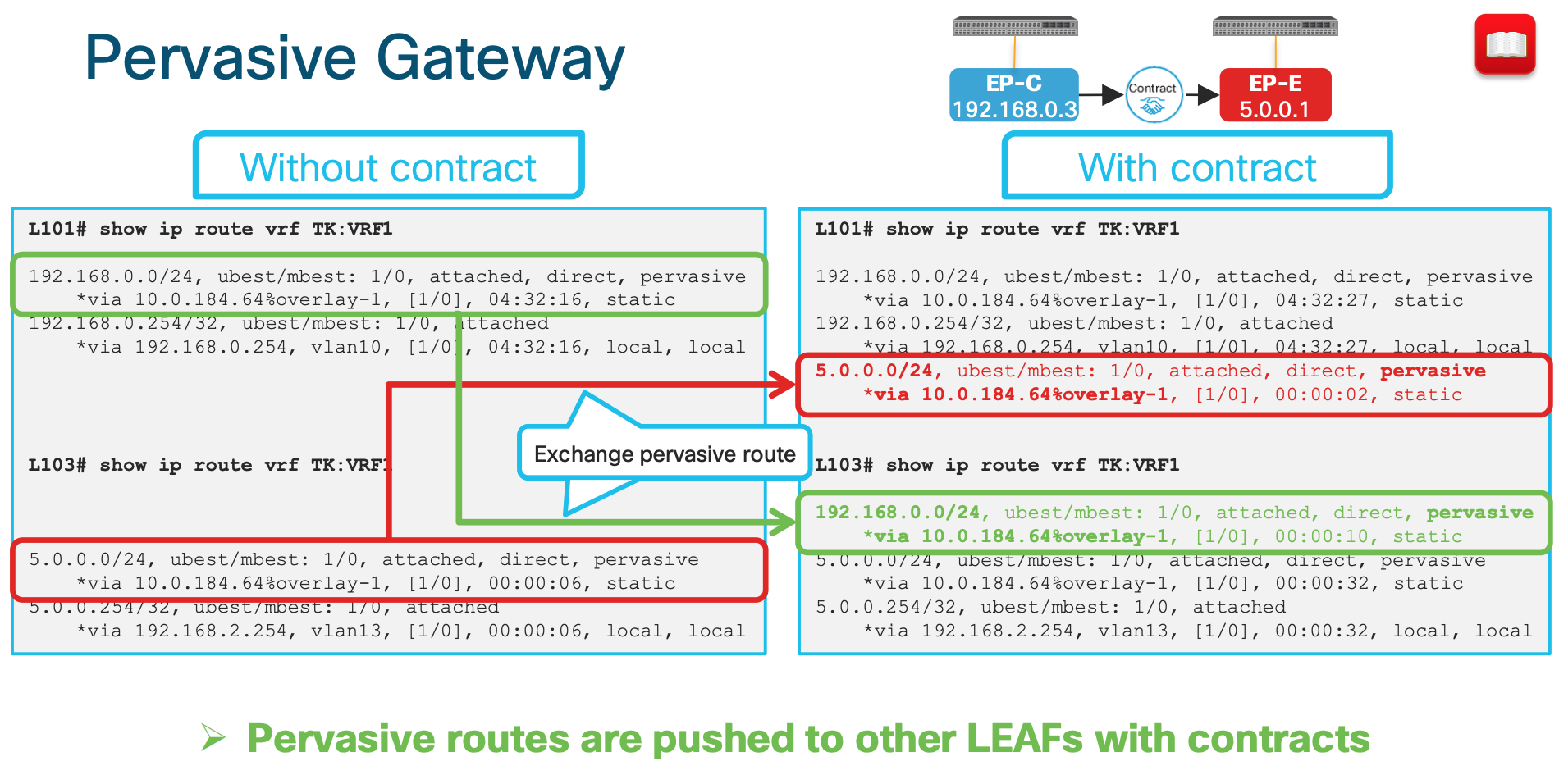
Now coming back to the question of Why does ACI push pervasive routes to other LEAFs after a contract?
###Without the pervasive route:
| WITHOUT Pervasive Route | WITH Pervasive Route |
|---|---|
| In the below example since there is no pervasive route the communication will not happen with EP-E from EP-C | In this case with the SPINE Proxy route EP-C can send the traffice to SPINE since it knows the path is via SPINE |
 |
 |
This is what the outputs looks like in CLI when the contract is applied:
ACI Forwarding Scope Concepts
This is one of the best slides showing the communication scenarios and whether its switched or routed. Look at the detailed explanation below:
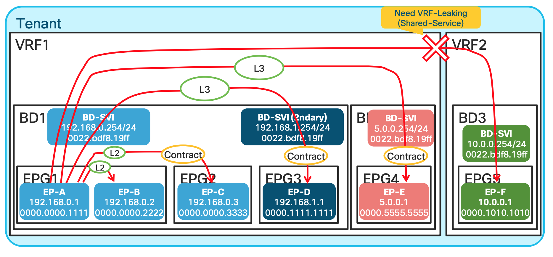
EP-A talking to EP-B: In this scenario , since both EPGs are in the same subnet and same L2 domain the traffic is Layer 2 Switched.EP-A talking to EP-C: Same Bridge domain but differen EPG , and has a contract , still L2 switched.EP-A talking to EP-D: Same BD , but different subnet ; hence L3 routed.EP-A talking to EP-E: Different BD and different network hence L3 switched.EP-A talking to EP-F: Differen VRF , unless route leaking is implemented no traffic communication happens.
ACI Lab Use Cases Walk Through
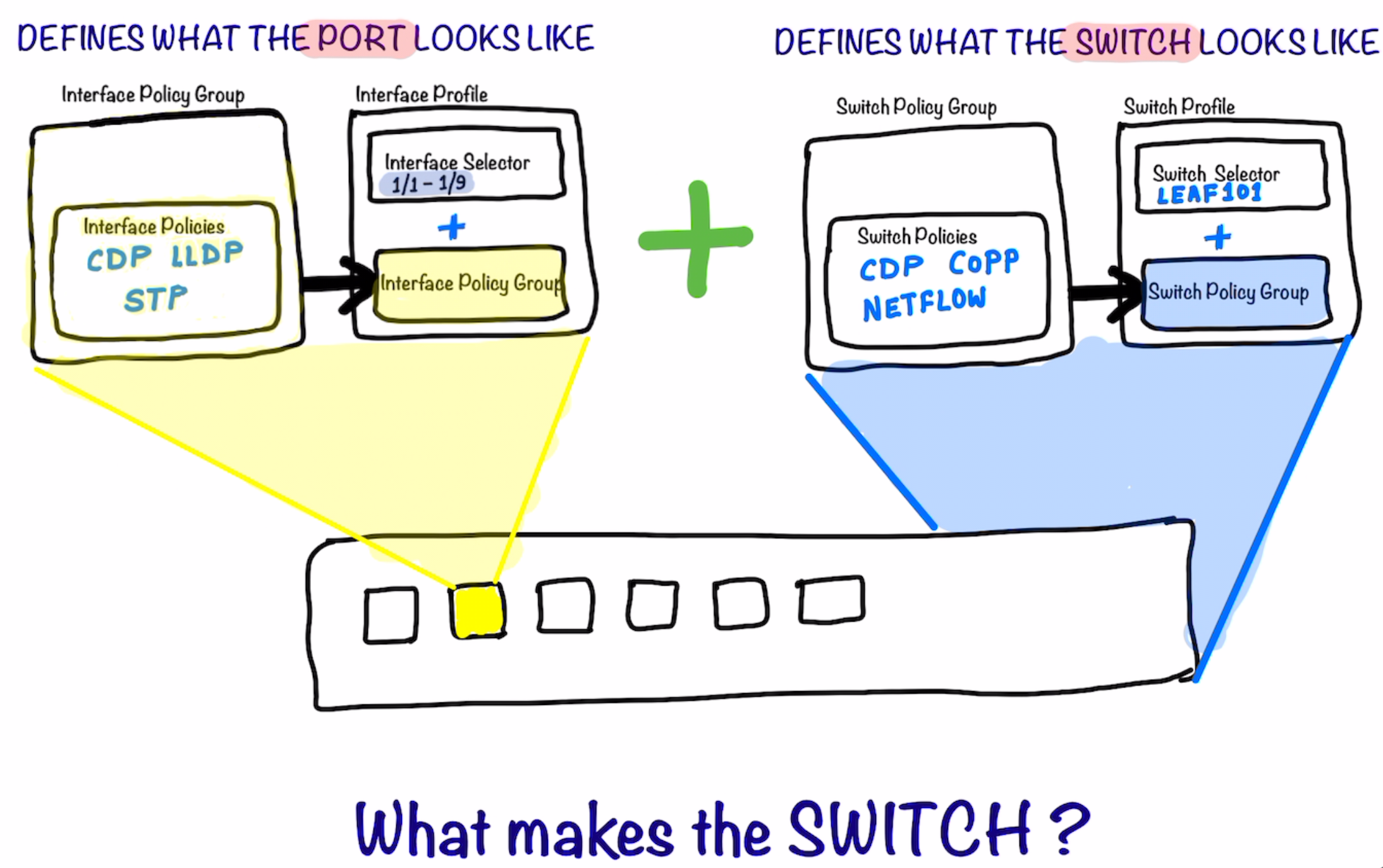
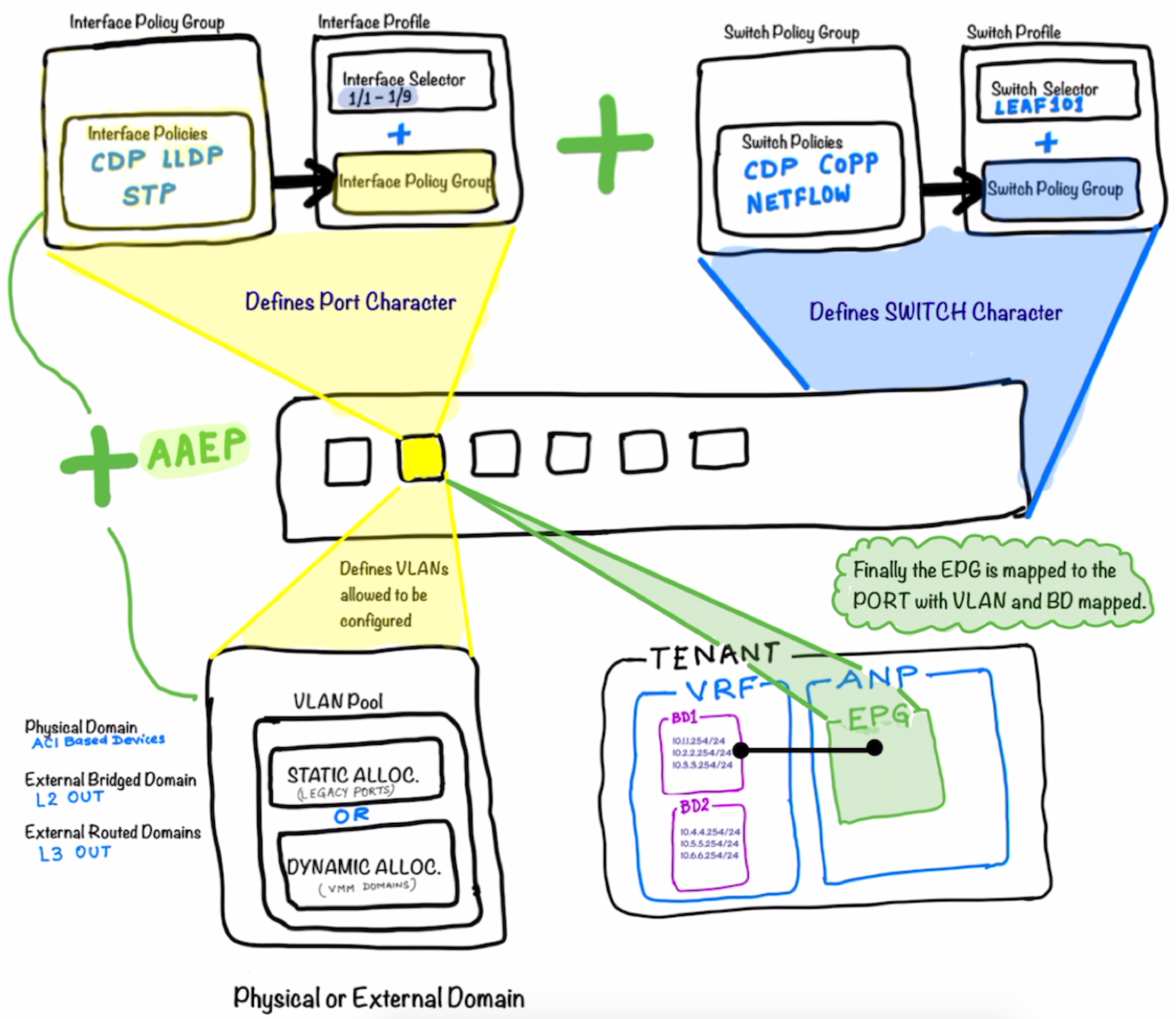
The following diagram illustrates what make a ACI Switch defined. Just like in UCS we define the Service Profile; In the Profile creating with ACI; the Interface Profile defines the characteristics of the Interfaces while the Switch Profile defines the characteristics of the Switch itself .
Joining the Interface Profile and Switch Profile together makes the whole Switch .
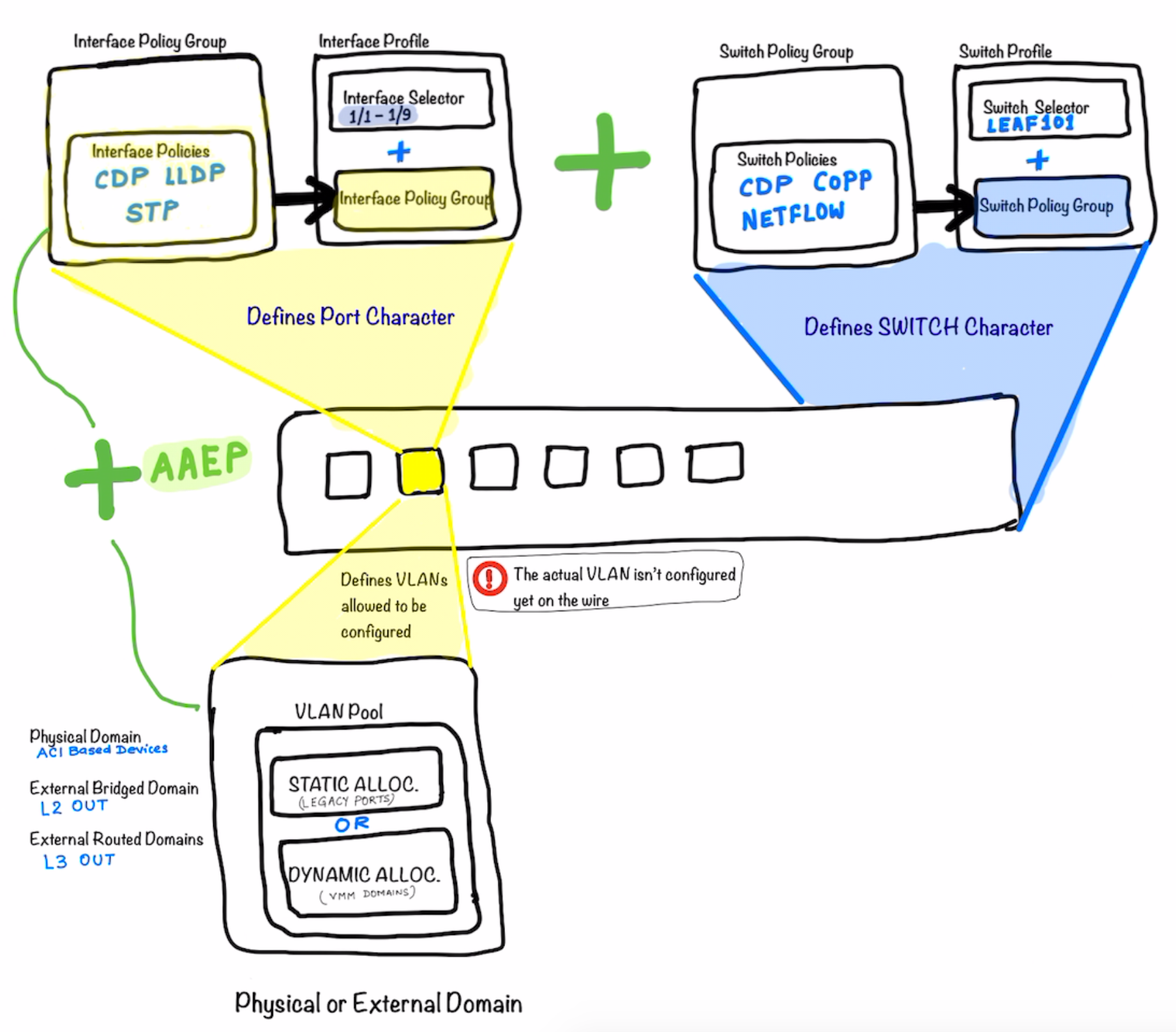
After the step above ; as a next step we start defining what are the VLANs that could be allowed on the port. Remember that these VLANs still are not assigned to the port. They are just the vlans which are being allowed to be configured/used on the port.
-
The Physical Domain is for ACI Based devices (Devices Residing on ACI)
- External Bridge Domain is for L2Out
- External Routed Domain is for L3Out
The External Domain and the allowed VLANs are now added to the Port Profile using AAEP ; which ties them together.
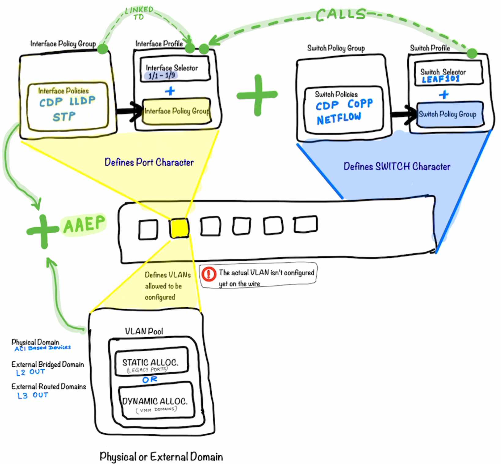
The picture below illustrates what’s explained above in more details. Look at how the different components are called and tied to each other .
The Switch Policy Group is tied to the Switch Profile which in turn is called-in in the Interface Profile .
The Interface Profile is then tied to the Interface Policy Group
Definitions of the Interface Policy Groups are key part of the ACI Configuration **Notice that in the top half of the picture the main components is the the
Interface Policy Group**
Now as a next step of progressing on the workflow above ; we create the Tenant under which the EPG is created and tied to the port which is the actual networking construct in ACI and completes the whole picture .
The picture illustrates that the Tenant is created ; under which the VRF and the Bridge Domains are created.
After that the Application Network Profile is created under which the EPG is defined.
This EPG is in the end tied to the the Bridge Domain completing the whole workflow.
Notice that there is no explicit mapping between the Switch Profile / Interface Profile configs and the Tenant Config (EPG) ; so do not confuse
What we cover
- Basic Setup [Fabric Setup]
- Tenant Setup [Tenant , VRF , Bridge Domain , Subnets]
- Creation of the EPGs
- Contracts
- L2OUT using standard port channel
- L2Out using VPC
- EPGs for L2 Out
- L3 Out Using OSPF
- EPGs for L3 Outs
- L3 Out for EIGRP
- Transit Routing
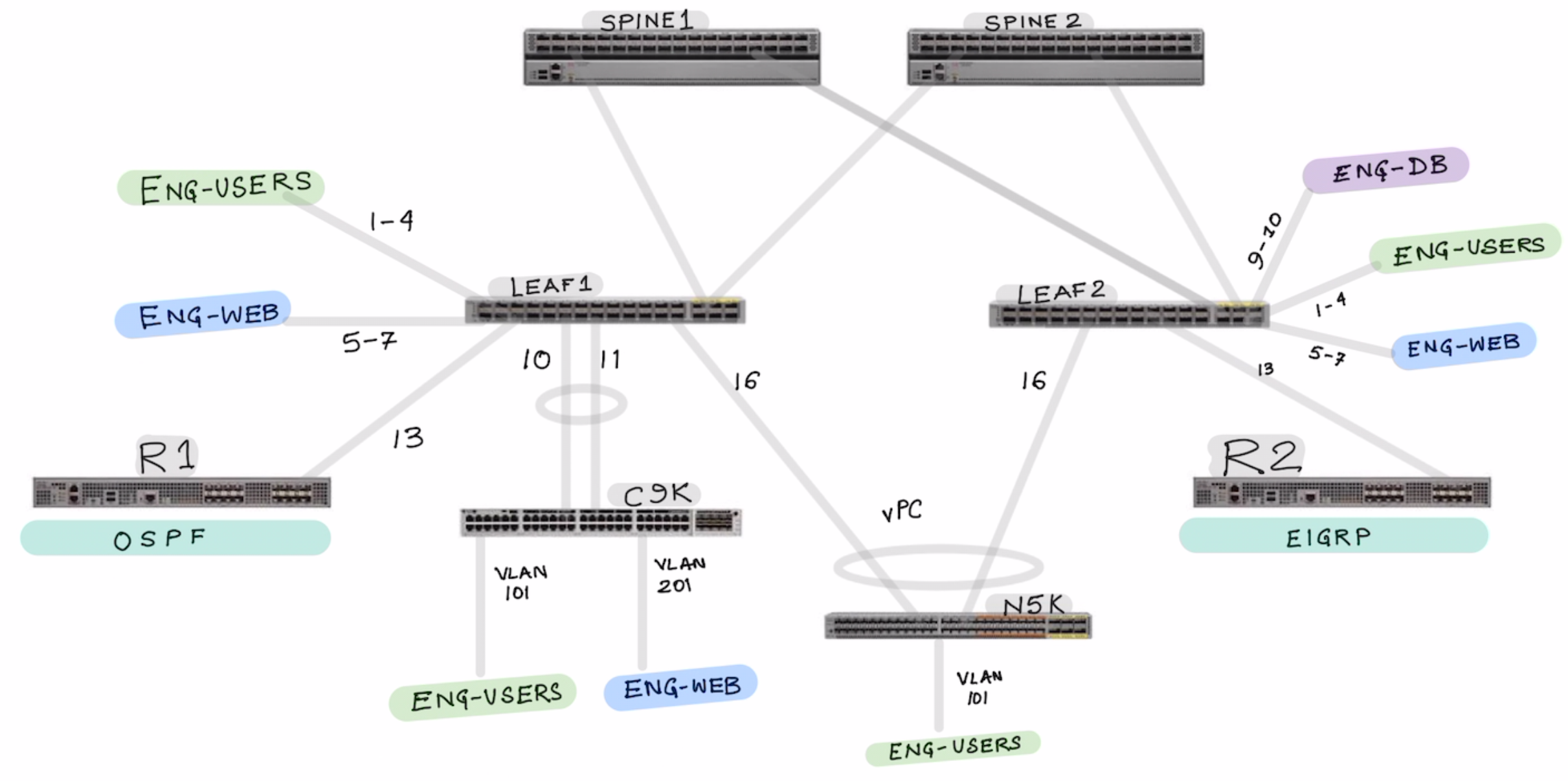
In the above topology we configure the following topics:
Part 1: Interface Policy Group and Interface Profile Configuration
Lets start by configuring the Interface Policy Group and Interface Profile
- IPG-ENG-USERS
- IPG-ENG-WEB-SERVERS
- IPG-ENG-DB-SERVERS
- IPG-ROUTER-1-OSPF
- IPG-ROUTER-2-EIGRP
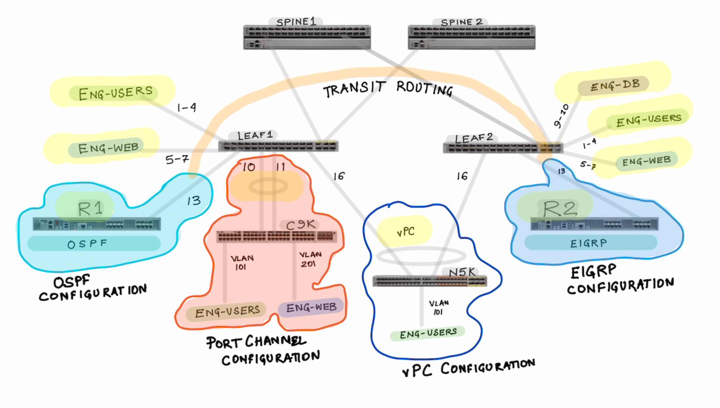
Notice how the port channels are differently created for Regular Port Channel and vPC based port-channel.
- IPG-PORT-CHANNEL-REGULAR
- IPG-VPC-PORT-CHANNEL-LEAF1-LEAF2
Show where you see the port-channels once they are created.
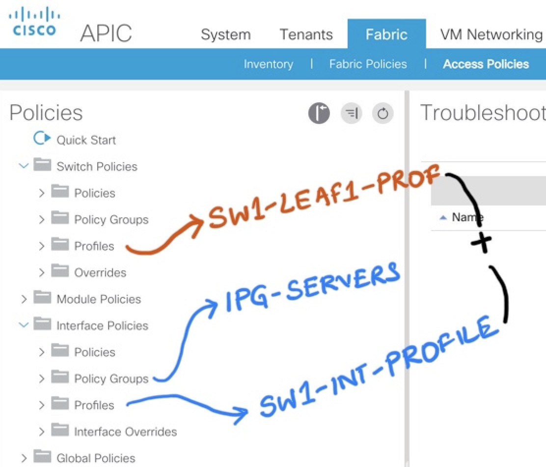
Now Lets configure the Interface Profiles
- Create the Interface Profile for Each Switches SW1-INT-PROFILE SW2-INT-PROFILE
Notice in the picture below , the interface profile is switch specific . It makes sense so that It can be tied to a specific switch profile.
VIDEO HERE OF THE ABOVE INTEFACE CONFIGURATIONS
Part 2: Switch Policy Group and Switch Profile Configuration
How to configure VPC and Map the interface configuration .
Subscribe via RSS