CCIE Security v5 Notes
by Vikas Srivastava
Opinions expressed are solely my own and do not express the views or opinions of my employer.
- VPN (Policy based) - Key Exchange Protocol
- GRE Tunnel - Step 1 - Step 2
- GRE over IPSec - Tunnel Mode
- GRE / IPSec - Transport Mode - Configuration - Native IPSec Tunnel [S-VTI] - MGRE (Multipoint GRE) - A Multipoint GRE Full Configuration Snippet
- DMVPN (Dynamic Multipoint VPN) - DMVPN - EIGRP - Phases [I,II,III] - Redundancy [Dual-Hub DMVPN Setup] - GETVPN - Configuration of a GETVPN - VRF - A Quick Introduction - Basic VRF Configuration Example - VRF Reachability test - VRF Routing configuration example - VRF - Aware VPNs - MAJOR DIFFERENCE IS IN THIS SECTION - BEGIN - MAJOR DIFFERENCE IS IN THIS SECTION - END
- * * * Lab Remaining from here * * * - VRF Aware [Get VPN]
- Routers as a CA Server
- IKEv2 VPNS
- Flex VPN
- ASA Firewalls
- NAT - #### Source Dynamic NAT Configuration Example #############
- Transparent Firewall
- ASA Redundancy
- Redundant Interfaces (Failover , Only one active)
- Redundant Interfaces (Port Channel , both interfaces active)
- Security Contexts [Virtual Firewalls]
- Failover
- ASA VPN Configuration (NAT-T)
- Clustering
- IKEv1 Site-to-Site on ASA (ASA to Router)
- IKEv2 Site-to-Site (Between ASA and IOS)
- Clientless WebVPN on ASA
- Firepower and FTD
- WSA (Web Security Agent)
- ESA (Email Security Agent)
- Cisco ASA with Anyconnect VPN using SSL or IKEv1/v2
- Cisco ISE
- Wireless
- Technotes - Troubleshooting Commands and Outputs - Error Messages and Resolution - Eve-NG Docker IP Address Configuration (in the Starup config of the docker )
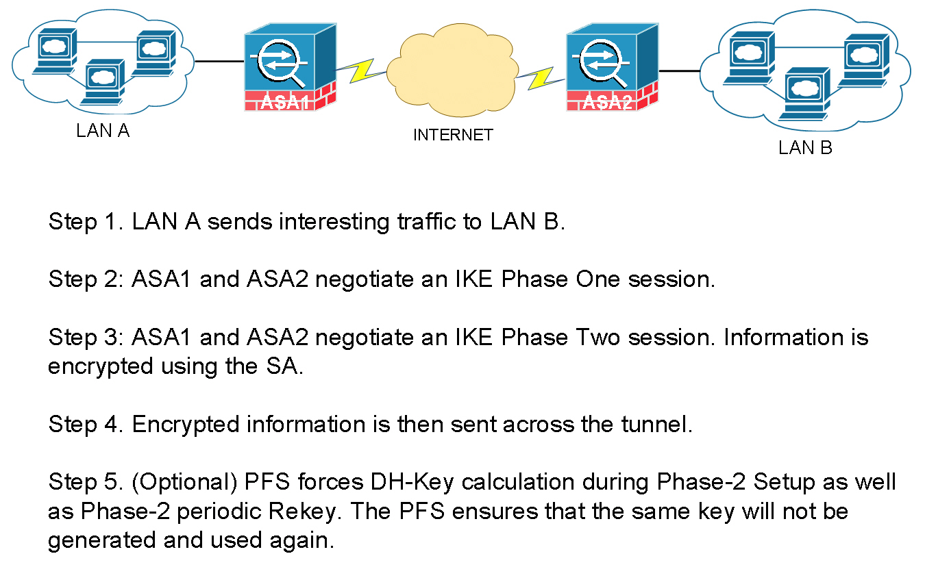
VPN (Policy based)
Key Exchange Protocol
For two sides to encrypt or decrypt the traffic , a key needs to be shared between two endpoints.
You need the following to secure a Tunnel :
- Key
- Encryption
- Hashing
Diffie Hellman is the algorith that generates a
KEY. Lifetime of a DH key is 3600 secs (1hr).
There are two tunnels :
PHASE 1The first tunnel is to exchange the KEY .ISAKMPInternet Security Association and Key Managment Protocol is used here .PHASE 2The second tunnel is for Data transfer.ESPEncapsulation Security Payload is used in this phase.
Though its not recommened , you can manually setup the
Phase 2tunnel to use a manual key skipping thePhase 1negotiation (without usingISAKMP).
Configuration example
1. Configure the Parameters for Phase 1
crypto isakmp policy 10
 auth pre-share   //KEY
 encryption 3des  //ENCRYTPION
 hash md5         //HASH
 group 2 // The group command actually generates the hey to be used in the second phase .

crytpto isakmp policy 20
 auth pre-share
 encrytption 3des
 hash sha
 group 2

crypto isakmp key cisco111 address 1.1.1.1
crypto isakmp key cisco111 address 2.2.2.2
2. Configure the Parameters for Phase 2 (only encryption and hash , as we have already got the key from phase 1)
crypto ipsec tranform-set TSET esp-3des esp-md5
3. Define traffic that will be encrypted over the Tunnel
access-list 101 permit 10.1.1.0 0.0.0.255 10.2.2.0 0.0.0.255
4. Finally Create a Crypto MAP to tie all of the above together
crypto map CMAP 5 ipsec-isakmp ! (5 is sequence number , and isakmp means  (get the key from Diffie-Hellman))
match address 101  //access-list
set peer 192.168.1.10
set transform-set TSET // Configured above
5. Apply on the interface
int fa0/0 crpypt map CMAP
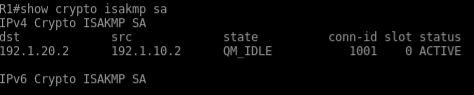
Always ping with ping source field show crypto ipsec sa show crpto isakmp sa
THe tunnel will stay up for :
Phase 1 86400 sec 24 hrs Phase 2 3600 sec 1 hr
In the above VPN Configuration , the interesting traffic is define by an
ACL. Such VPNs are called Policy based VPN.
GRE Tunnel
GRE Tunnel basically creates a virtual point to point link between two routers which traditionally were establishing VPN based on interesting traffic define by ACLs . Which was a tedious process.
Here is the sample configuration of a GRE Tunnel. It is basically a two step process
-
Creat a virtual link between the two routers , in this example R1 and R2
-
Now since they are “virtually” directly connected , you can run a routing protocol to exchange routing information directly within them.
Step 1
R1
interface tun0
 ip add 192.168.1.1 255.255.255.0
 tunnel source 192.1.10.2
 tunnel destination 192.1.20.2
R2
interface tun0
 ip add 192.168.1.2 255.255.255.0
 tunnel source 192.1.20.2
 tunnel destination 192.1.10.2
Step 2
Now you can run a routing protocol of choice to make them talk
!
router eigrp 10
 network 10.0.0.0
 network 192.168.1.0
 no auto-summary
!
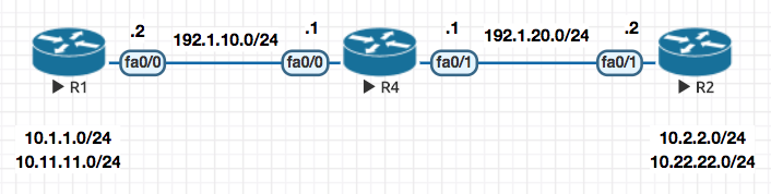
GRE over IPSec - Tunnel Mode
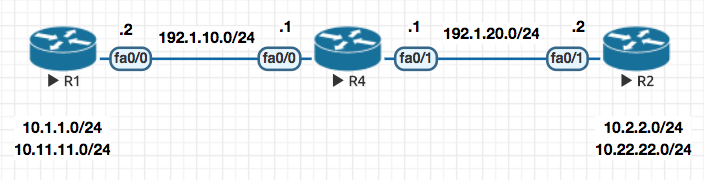
In this mode once the GRE tunnel is up , we basically apply the Crypto Map configuration as a profile to the tunnel interface (in this e.g IPROF )
Notice that there is no need to define
matchfor interesting traffic orset-peeras this is all taken care by thetunnel0interface by default as every traffic via the tunnel interface is interesting and the peer (set peer) is known because of GRE. .
! R1
! Configure Phase I

crypto isakmp policy 10
 auth pre-share
 encryption 3des
 hash md5
 group 2

crypto isakmp key cisco123 address 192.1.20.2


! Configure Phase II

crypto ipsec transform-set TSET esp-3des esp-md5

! Configure an IPSec Profile and attach the transform-set to it

crypto ipsec profile IPROF
 set transform-set TSET

! Assign the IPSec Profile to the Tunnel interface

interface tunnel0
  tunnel protection ipsec profile IPROF
! R2
! Configure Phase I

crypto isakmp policy 10
 auth pre-share
 encryption 3des
 hash md5
 group 2

crypto isakmp key cisco123 address 192.1.10.2


! Configure Phase II

crypto ipsec transform-set TSET esp-3des esp-md5

! Configure an IPSec Profile and attach the transform-set to it

crypto ipsec profile IPROF
 set transform-set TSET

! Assign the IPSec Profile to the Tunnel interface

interface tunnel0
  tunnel protection ipsec profile IPROF
Now notice that in the plain simple GRE the packet looked like this , which totaled 88 bytes:
+----+------------+------------+-------+-------------+------------+------+
|GRE | 192.1.10.1 | 192.1.20.3 | EIGRP | 192.168.1.1 | 224.0.0.10 | Data |
+----+------------+------------+-------+-------------+------------+------+
With IPSec enable on it (which we did in the config example above) the packet size increase to 140 bytes because of the ESP header and now looks like this :
+----------------+-----------------+------------+------------+-------+-------------+------------+------+
|ESP| 192.1.10.X | 192.1.20.X| GRE | 192.1.10.1 | 192.1.20.3 | EIGRP | 192.168.1.1 | 224.0.0.10 | Data |
+----------------+-----------------+------------+------------+-------+-------------+------------+------+
In the above packet , the entire packet including GRE is just a
datapacket (encapsulated in the ESP).
So the overhead is that you have increased the size of the packet by 52 bytes (140 - 88 = 52 ) .
Tunnel Mode is the default mode for IPSec .
Notice the tunnel in output
show crypto ipsec sa

outbound esp sas:
 spi: 0x99D47D47(2580839751)
   transform: esp-3des esp-md5-hmac ,
   in use settings ={Tunnel, }
Now if you GRE and ESP header are the same , you can run IPSec in Tranport Mode
In transport mode , it will remove the duplication of ESP and GRE header and make the packet smaller .
GRE / IPSec - Transport Mode
An efficient mode over Tunnel Mode and saves some overhead on encryption
So with above theory
+----------------+-----------------+------------+------------+-------+-------------+------------+------+
|ESP| 192.1.10.X | 192.1.20.X| GRE | 192.1.10.1 | 192.1.20.3 | EIGRP | 192.168.1.1 | 224.0.0.10 | Data |
+----------------+-----------------+------------+------------+-------+-------------+------------+------+
Changes to
+----------------+-----------------+-------+-------------+------------+------+
|ESP| 192.1.10.X | 192.1.20.X| GRE | EIGRP | 192.168.1.1 | 224.0.0.10 | Data |
+----------------+-----------------+-------+-------------+------------+------+
Above changes saves 16 bytes for you , so now your packet size becomes 140 - 16 = 124
Configuration
The configuration of the transport mode is similar to the tunnel mode , the only change is highlighted below (mode transport)
crypto ipsec transform-set TSET esp-3des esp-md5
 mode transport

clear crypto sa
Native IPSec Tunnel [S-VTI]
Also know as Static Virtual TUnnel Interface
Now continuing on to the above flow , is GRE required for the IPSec ? Cant we run the IPSec over the tunnel interface without GRE ? The answer to that is yes and we basically
interface tunnel0
 tunnel mode ipsec ipv4
So what benefit did the above change provide ?
The packet changed from
ESP| 192.1.10.X | 192.1.20.X| GRE | EIGRP | 192.168.1.1 | 224.0.0.10 | Data |
to (remove of GRE header , 8 bytes)
ESP| 192.1.10.X | 192.1.20.X| EIGRP | 192.168.1.1 | 224.0.0.10 | Data |
Above changes saves 8 bytes for you , so now your packet size becomes 124 - 8 = 116
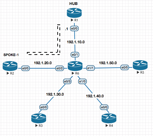
MGRE (Multipoint GRE)
The point to point configuration setting above does not scale with a lot of sites , that is where MGRE comes to rescue.
Now since in GRE we had to define the tunnel destination address: tunnel destination X.X.X.X
Since in this case , their could be multiple destinations we need to use a mapping table which maps destination to be reached to the next hop address to be used . This system is called NHRP (Next Hop Resolution Protocol)
ip nhrp map 192.168.1.1 192.1.10.1
The above command means that if I want to go to 192.168.1.1 the public IP address for the same is 192.1.10.1
interface tunnel0
 ip address 192.168.1.1
 tunnel source 192.168.20.2
 tunnel mode gre multipoint
 ip nhrp network-id 1
 ip nhrp map 192.168.1.1 192.1.10.1
 ip nhrp map 192.168.1.2 192.1.20.2
 ip nhrp map 192.168.1.3 192.1.30.3
A Multipoint GRE Full Configuration Snippet
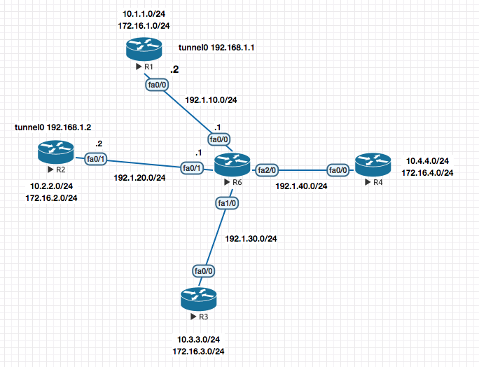
! R1

interface tunnel0
 ip address 192.168.1.1 255.255.255.0
 tunnel source 192.1.10.2
 tunnel mode gre multipoint
 ip nhrp network-id 1
 ip nhrp map 192.168.1.2 192.1.20.2
 ip nhrp map 192.168.1.3 192.1.30.2
 ip nhrp map 192.168.1.4 192.1.40.2


!R2

interface tunnel0
 ip address 192.168.1.2 255.255.255.0
 tunnel source 192.1.20.2
 tunnel mode gre multipoint
 ip nhrp network-id 1
 ip nhrp map 192.168.1.1  192.1.10.2
 ip nhrp map 192.168.1.3  192.1.30.2
 ip nhrp map 192.168.1.4  192.1.40.2


! R3

interface tunnel0
  ip address 192.168.1.3 255.255.255.0
  tunnel source 192.1.30.2
  tunnel mode gre multipoint
  ip nhrp network-id 1
  ip nhrp map 192.168.1.1 192.1.10.2
  ip nhrp map 192.168.1.2 192.1.20.2
  ip nhrp map 192.168.1.4 192.1.40.2


! R4

interface tunnel0
  ip address 192.168.1.4 255.255.255.0
  tunnel source 192.1.40.2
  tunnel mode gre multipoint
  ip nhrp network-id 1
  ip nhrp map 192.168.1.1 192.1.10.2
  ip nhrp map 192.168.1.2 192.1.20.2
  ip nhrp map 192.168.1.3 192.1.30.2
R1#show ip nhrp
192.168.1.2/32 via 192.168.1.2, Tunnel0 created 00:08:03, never expire
  Type: static, Flags: used
  NBMA address: 192.1.20.2
192.168.1.3/32 via 192.168.1.3, Tunnel0 created 00:08:03, never expire
  Type: static, Flags: used
  NBMA address: 192.1.30.2
192.168.1.4/32 via 192.168.1.4, Tunnel0 created 00:08:03, never expire
  Type: static, Flags: used
  NBMA address: 192.1.40.2
R1#
DISADVANTAGES In this type of NHRP Based name resolution you need to statically define the mapping which is not scalable and also requires all sites to have static IP Addressing.
Now this disadvantage was eliminiated by the use of a Next Hop Server like a DNS naming server.
How does the Next Hop Server works ?
Under the inteface configuration on the end routers , we define the Next Hop Servers IP Address. When these interfaces come up they register their information to the Next Hop Server notifying :
“Hey my Tunnel address is X.X.X.X and my Public address is Y.Y.Y.Y “
Now the NHS Server has all the mapping of Tunnel IP and the Public IP .
DMVPN (Dynamic Multipoint VPN)
How does the Next Hop Server works ?
Under the inteface configuration on the end routers , we define the Next Hop Servers IP Address. When these interfaces come up they register their information to the Next Hop Server.
Step 1. Enabling the Next Hop Server
! R1

interface tunnel0
 ip address 192.168.1.1 255.255.255.0
 tunnel source f0/0
 tunnel mode gre multipoint
 ip nhrp network-id 1
 ip nhrp map multicast dynamic // For sending the reply for EIGRP packets received from clients , the NHS Server knows who to send the reply by looking at the dynamic NHRP table.

router eigrp 100
 no auto
 network 10.0.0.0
 network 192.168.1.0
 network 172.16.0.0
That’s all for configuring a NHS!
Step 2. Configuring the Next Hop Client
! R2

interface tunnel0
 ip address 192.168.1.2 255.255.255.0
 tunnel source f0/1
 tunnel mode gre multipoint
 ip nhrp network-id 1
 ip nhrp nhs 192.168.1.1
 ip nhrp map 192.168.1.1  192.1.10.2 // How do I reach the NHS ? This line basically points every client to the Next Hop Server.
 ip nhrp map multicast 192.1.10.2 // For the EIGRP Packets

 router eigrp 100
  no auto
  network 10.0.0.0
  network 192.168.1.0
  network 172.16.0.0
Repeat the above configuration for other Clients on the DMVPN.
R1#sh ip nhrp
192.168.1.2/32 via 192.168.1.2, Tunnel0 created 00:00:12, expire 01:59:47
  Type: dynamic, Flags: unique registered used
  NBMA address: 192.1.20.2
This completes your DMVP Configuration.
DMVPN - EIGRP - Phases [I,II,III]
Phase I - With the default configuration of DMVPN only the neighborship is formed between Hub and Spoke routers but not between Spoke and Spoke directly.
To resolve this we to turn off split-horizon on the hub.
Split Horizon, dont send the update back on the same interface you learned the route on.
interface tunnel0
 no ip split-horizon eigrp 100
BEFORE (without the split-horizon configured)
R2#sh ip route eigrp
     172.16.0.0/24 is subnetted, 2 subnets
D       172.16.1.0 [90/297372416] via 192.168.1.1, 00:10:13, Tunnel0
     10.0.0.0/24 is subnetted, 2 subnets
D       10.1.1.0 [90/297372416] via 192.168.1.1, 00:10:13, Tunnel0
AFTER (after the split-horizon configured)
R2#sh ip route eigrp
     172.16.0.0/24 is subnetted, 4 subnets
D       172.16.4.0 [90/310172416] via 192.168.1.1, 00:00:08, Tunnel0
D       172.16.1.0 [90/297372416] via 192.168.1.1, 00:18:44, Tunnel0
D       172.16.3.0 [90/310172416] via 192.168.1.1, 00:00:08, Tunnel0
     10.0.0.0/24 is subnetted, 4 subnets
D       10.4.4.0 [90/310172416] via 192.168.1.1, 00:00:08, Tunnel0
D       10.3.3.0 [90/310172416] via 192.168.1.1, 00:00:08, Tunnel0
D       10.1.1.0 [90/297372416] via 192.168.1.1, 00:18:44, Tunnel0
Phase II (Traffic from Spoke to Spoke goes direct) - Second you would like the traffic to be point to point and not hoping thorough the NHS Router (look at the putput above where all traffic is hopping through 192.168.1.1).
Notice the traffic is going via 192.168.1.1
R3#traceroute 10.2.2.1

Type escape sequence to abort.
Tracing the route to 10.2.2.1

  1 192.168.1.1 20 msec 20 msec 20 msec
  2 192.168.1.2 32 msec *  48 msec
R3#
The resolution of this issue is to ensure that the next-hop isnt changed. In the above example
R2toldR1about its routes first.- Then R1 tells
R3about its routes , here it changes thenext-hopfor addresss learned fromR2to itself .
interface tunnel0
 no ip next-hop-self eigrp 100
BEFORE (All traffic going via 192.168.1.1)
R2#sh ip route eigrp
     172.16.0.0/24 is subnetted, 4 subnets
D       172.16.4.0 [90/310172416] via 192.168.1.1, 00:00:08, Tunnel0
D       172.16.1.0 [90/297372416] via 192.168.1.1, 00:18:44, Tunnel0
D       172.16.3.0 [90/310172416] via 192.168.1.1, 00:00:08, Tunnel0
     10.0.0.0/24 is subnetted, 4 subnets
D       10.4.4.0 [90/310172416] via 192.168.1.1, 00:00:08, Tunnel0
D       10.3.3.0 [90/310172416] via 192.168.1.1, 00:00:08, Tunnel0
D       10.1.1.0 [90/297372416] via 192.168.1.1, 00:18:44, Tunnel0
AFTER ( Now , all site specific traffic goes to the specific sites router without hopping over 192.168.1.1)
R2#sh ip route eigrp
     172.16.0.0/24 is subnetted, 4 subnets
D       172.16.4.0 [90/310172416] via 192.168.1.4, 00:00:30, Tunnel0
D       172.16.1.0 [90/297372416] via 192.168.1.1, 00:00:30, Tunnel0
D       172.16.3.0 [90/310172416] via 192.168.1.3, 00:00:30, Tunnel0
     10.0.0.0/24 is subnetted, 4 subnets
D       10.4.4.0 [90/310172416] via 192.168.1.4, 00:00:30, Tunnel0
D       10.3.3.0 [90/310172416] via 192.168.1.3, 00:00:30, Tunnel0
D       10.1.1.0 [90/297372416] via 192.168.1.1, 00:00:30, Tunnel0
Phase III -
In this phase NHRP basically redirects Spokes to reach directly out to other spokes its tryign to reach.
The NHS Server points the spokes to where they are trying to reach and installs a NHRP Cache entry pointing towards that remote spoke in the requesting spoke.
! HUB
ip nhrp redirect
! SPOKES
ip nhrp shortcut
So with this , only the first NHRP resolution request is sent to R1 and the remaining data flow happens directly
R4#trace 10.3.3.1

Type escape sequence to abort.
Tracing the route to 10.3.3.1

  1 192.168.1.1 28 msec 40 msec
    192.168.1.3 24 msec
R4#trace 10.3.3.1

Type escape sequence to abort.
Tracing the route to 10.3.3.1

  1 192.168.1.3 32 msec *  40 msec
Redundancy [Dual-Hub DMVPN Setup]
In this case you basically copy the configuration of the existing NHS , make a new NHS . Point each other NHS with a MAP command and run routing protocol on both .
After this you point your spokes to the additional NHS . Pretty basic stuff .
Encrypting the Tunnel using IPSEC
!1. Phase 1

crypto isakmp policy 10
 auth pre-share
 hash md5
 encryption 3des
 crypto isakmp key cisco123 address 0.0.0.0

 !2. Phase 2

 crypto ipsec transform-set TSET esp-3des esp-md5
  mode transport
  exit

!3. IPSec Profile

 crypto ipsec profile PROF
  set transform-set TSET
  exit

!4. Apply the profile to the interface

 interface tunnel 0
  tunnel protection ipsec profile PROF
GETVPN
GetVPN is a Cisco only solution
GETVPNS are used in a MPLS Private WAN type deployments as the GETVPNs packets cannot be routed over the internet.
Why do we need GETVPNs when we have DMVPN : THe purpose to ket full encryption capabilities while the routing is already setup.
GetVPN copies the inner header onto the outer header. It only works on fully routed networks. It can potentially work on the Internet but only if you are using Public addresses on the inside .
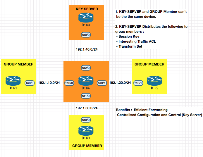
A multisite IPSec VPN uses a single session key for multiple sites . It has two entities ; Key Server and Group Member
Session key is exchanged in
Phase 1and used inPhase 2
In a normal Phase 1 (ISA) , the only thing exchanges happens is the session key.
ISAKMP This protocol only echanges Session Key . Run on UDP/500
GDOI (Group Domain of Interpretation) : This Exchanges Session Key , Interesting Traffic ACL, Transform Set and is specially made for GETVPNs. Runs on UDP/848 . This protocol is like an extension for ISAKMP.
In GETVPNs ,
PHASE 1 is setup between Group Member and Key Server .
PHASE 2 is setup between Group Member and Group Member
Prerquisite for GETVPN : Make sure all networks are able to reach all networks
Configuration of a GETVPN
Step 1. Configure the Key Server
! KEY SERVER

! 1. Phase I

crypto isakmp policy 10
 auth pre-share
 hash md5
 enc 3des
 group 2

crypto isakmp key cisco123 address 192.1.10.2
crypto isakmp key cisco123 address 192.1.20.2
crypto isakmp key cisco123 address 192.1.30.2

! 2. Phase II

crypto ipsec transform-set TSET esp-3des esp-sha-hmac

! 3. Configure IPSEC Profile

crypto ipsec profile IPROF
 set transform-set TSET

! 4. Configure Interesting traffic ACL

access-list 101 permit ip 10.1.0.0 0.0.255.255 10.1.0.0 0.0.255.255

! 5. Configure the GDOI Group Configuration

crypto gdoi group SALES
 identity number 111 ! Should match on the Group members
 server local ! I am the key server , so local
  sa ipsec 10
   profile IPROF
   match address ipv4 101
address ipv4 192.1.40.2
Step 1. Configure the Group Members
!R1

! 1. Phase I

crypto isakmp policy 10
 auth pre-share
 hash md5
 enc 3des
 group 2

crypto isakmp key cisco123 address 192.1.40.2

! 2. Configure GDOI to point to the Key Server

crypto gdoi group GRP-R1
 identity number 111 ! Should match on the Group members
 server address ipv4 192.1.40.2 ! Point to the key server

! 3. Configure a Crypto MAP

crypto map CMAP 10 gdoi
 set group GRP-R1

! 4. Apply Crypto MAP to the outgoing interface
int f0/0
 crypto map CMAP ! As soon as you do this , the key is downloaded.
Once you enter the above configuration on the Group member you will see the following output on the member :
*Mar  1 01:12:10.919: %CRYPTO-5-GM_REGSTER: Start registration to KS 192.1.40.2 for group GRP-R1 using address 192.1.10.2
*Mar  1 01:12:10.947: %CRYPTO-6-GDOI_ON_OFF: GDOI is ON
*Mar  1 01:12:11.711: %GDOI-5-GM_REGS_COMPL: Registration to KS 192.1.40.2 complete for group GRP-R1 using address 192.1.10.2
Verification Commands
R4-KEYSERVER#show crypto gdoi ks members

Group Member Information :

Number of rekeys sent for group SALES : 0

Group Member ID   : 192.1.10.2
Group ID          : 111
Group Name        : SALES
Key Server ID     : 192.1.40.2

Group Member ID   : 192.1.20.2
Group ID          : 111
Group Name        : SALES
Key Server ID     : 192.1.40.2

Group Member ID   : 192.1.30.2
Group ID          : 111
Group Name        : SALES
Key Server ID     : 192.1.40.2

R4-KEYSERVER#show crypto gdoi
GROUP INFORMATION

    Group Name               : SALES (Multicast)
    Group Identity           : 111
    Group Members            : 0
    IPSec SA Direction       : Both
    Active Group Server      : Local
    Group Rekey Lifetime     : 86400 secs
    Rekey Retransmit Period  : 10 secs
    Rekey Retransmit Attempts: 2

      IPSec SA Number        : 10
      IPSec SA Rekey Lifetime: 3600 secs
      Profile Name           : IPROF
      Replay method          : Count Based
      Replay Window Size     : 64
      ACL Configured         : access-list 101

    Group Server list        : Local
Re-keyeing :
The lifetime of a key is 3600s , the lifetime counter starts when the first group member registers and a key is handed over.
Let’s say when a Group Member G1 registers to Key Server KS , the Key K1 is handed over with a count down timer started.
After 5 minutes (300sec) another Group Member G2 registers , it will be handed over the same key as G1 but the time remaining on it will be 3600-300=3300 secs.
OR
You can configure RE-KEYING , which basically sends a new key to everyone when a new Group Members join . This can be done over UNICAST or MULTICAST.
Re-Keyeing Configuration (Only done on Key Server)
Step 1. Generate a RSA Keypair on the Key Server
crypto key generate rsa modulus 1024 label GETVPN-KEY
Step 2. Configre the GDOI group for re-keyeing
crypto gdoi group SALES
 server local
 rekey transport unicast
 rekey authentication mypubkey rsa GETVPN-KEY
 rekey algorithm 3des-cbc
 rekey lifetime seconds 3600
VRF - A Quick Introduction
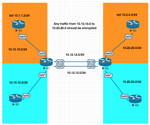
Basic VRF Configuration Example
!R1
conf t
ip vrf CUST-A
exit
ip vrf CUST-B
exit

int fa1/0
 ip vrf forwarding CUST-A
 ip address 10.12.12.1 255.255.255.0
 no shut
int fa2/0
 ip vrf forwarding CUST-B
 ip address 10.12.12.1 255.255.255.0
 no shut
int fa0/0
 ip vrf forwarding CUST-A
 ip address 10.10.10.1 255.255.255.0
 no shut
int fa0/1
 ip vrf forwarding CUST-B
 ip address 10.10.10.1 255.255.255.0
 no shut
VRF Reachability test
R1#ping vrf CUST-A ip 10.10.10.3

Type escape sequence to abort.
Sending 5, 100-byte ICMP Echos to 10.10.10.3, timeout is 2 seconds:
!!!!!
Success rate is 100 percent (5/5), round-trip min/avg/max = 12/18/24 ms
VRF Routing configuration example
router eigrp 1
 auto-summary
 !
 address-family ipv4 vrf CUST-B
  network 10.0.0.0
  no auto-summary
  autonomous-system 200
 exit-address-family
 !
 address-family ipv4 vrf CUST-A
  network 10.0.0.0
  auto-summary
  autonomous-system 100
 exit-address-family
VRF - Aware VPNs
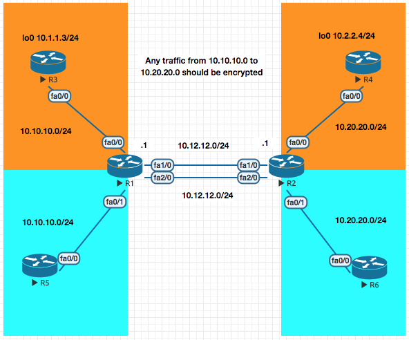
Now in the VRF example above the traffic between the loopback networks 10.1.1.3 to 10.2.2.4 is no encrypted. In this section we will enxrypt the data.
Objective R1 and R2 should encrypt traffic between 10.1.1.3 to 10.2.2.4.
Only R1 Config is displayed for brevity. Replicate the config for R2 changing the IP Addresses.
! R1
! 1. Phase I
! A. ISAKMP Policies
crypto isakmp policy 10
 auth pre-share
 hash md5
 enc 3des
 group 2

#### MAJOR DIFFERENCE IS IN THIS SECTION - BEGIN

! B. Create the Keyring
crypto keyring KR-1 vrf CUST-A
 pre-shared-key address 10.12.12.1 key cisco123

! C. Create an ISAKMP Profile which later on will be linked to crytpto map
crypto isakmp profile PROF-A
 vrf CUST-A
 keyring KR-1
 match identity address 10.12.12.1 255.255.255.255 CUST-A

#### MAJOR DIFFERENCE IS IN THIS SECTION - END

! 2. Phase II
crypto ipsec transform-set TSET esp-3des esp-md5

! 3. Interesting traffic
access-list 101 permit ip 10.2.2.0 0.0.0.255 10.1.1.0 0.0.0.255

! 4. Crpto MAP
crypto map CUST-A 10 ipsec-isakmp
 match address 101
 set peer 10.12.12.1
 set transform-set TSET
crypto map CUST-A isakmp-profile PROF-A

! 5. Apply the Crypto map to the interface
interface fa1/0
 crypto map CUST-A
Always ensure a source ping
R3#ping 10.2.2.4 source 10.1.1.3

Type escape sequence to abort.
Sending 5, 100-byte ICMP Echos to 10.2.2.4, timeout is 2 seconds:
Packet sent with a source address of 10.1.1.3
.!!!!
Success rate is 80 percent (4/5), round-trip min/avg/max = 28/41/56 ms
* * * Lab Remaining from here * * *
VRF Aware [Get VPN]
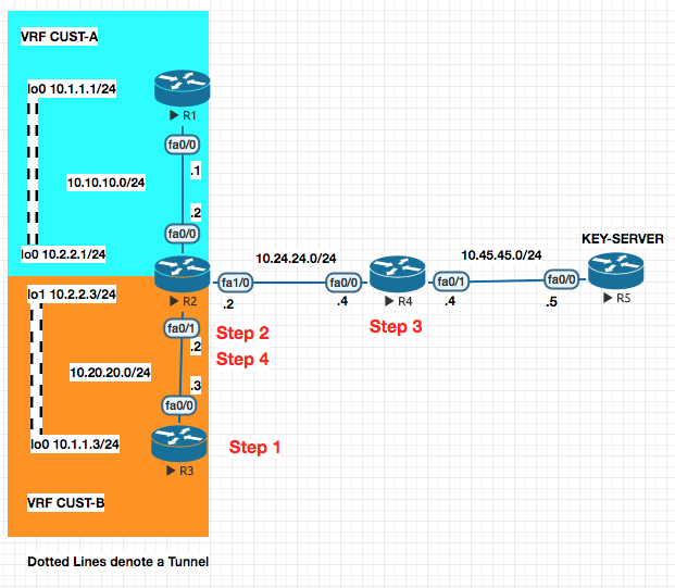
PREFACE : In the above configuration the once the IP Addressing is setup , there is EIGRP neighborship configured withing a VRF in the colored areas and the interfaces (no VRF on the R1 or R3 , only on R2).
With this , R1 and R3 cannot reach the Key Server . To enable that we have to configure the following (route-leaking) so that the networks behind R1 and R3 can reach the Key Server . The eventual goal is to encrypt traffic between R1 and R2 and R1 and R3 .
The config below is to make R3 reach R5 (Key Server)
Step 1. R3 —> R2
ip route 10.45.45.5 255.255.255.255 10.20.20.2
Step 2. R2 —-> R4 From VRF to Global Table and pointing to R4 (Next Hop)
ip route vrf CUST-B 10.45.45.45.5 255.255.255.255 fa1/0 10.24.24.4
Step 3. Back from R4 to R2
ip route 10.20.20.0 255.255.255.0 10.24.24.2
Step 4. From Global Routing table to VRF Routing Table for CUST-B
ip route 10.20.20.0 255.255.255.0 fa0/1
Now lets configure the VPN .
GET VPN Configuration
On the Key Server for Group CUST-A[100] and Group CUST-B[200]
! R5
!1. PHASE I
crypto isakmp policy 10
 auth pre-share
 hash md5
 group 2
 encryption 3des
!
crypto isakmp key cisco123 address 10.10.10.0 255.255.255.0
crypto isakmp key cisco123 address 10.20.20.0 255.255.255.0

!2. Phase II

crypto ipsec transform-set CUST-A esp-3des esp-md5-hmac
crypto ipsec transform-set CUST-B esp-3des esp-md5-hmac

!3. IPSec Profile

crypto ipsec profile PROF-A
 set transform-set CUST-A
crypto ipsec profile PROF-B
set transform-set CUST-B

!4. Interesting traffic ACL

access-list 101 permit ip 10.0.0.0 0.255.255.255 10.0.0.0 0.255.255.255
access-list 102 permit ip 10.0.0.0 0.255.255.255 10.0.0.0 0.255.255.255

!5. Configure the GDOI Groups

crypto gdoi group CUST-A
 identity number 100
 server local
  sa ipsec 10
   profile PROF-A
   match address ipv4 101
  address ipv4 10.45.45.5

crypto gdoi group CUST-B
 identity number 200
 server local
  sa ipsec 10
   profile PROF-B
   match address ipv4 102
  address ipv4 10.45.45.5
On the Group Members R1 and R3 (non-Vrf Configuration)
! R1
!1. PHASE I
crypto isakmp policy 10
 auth pre-share
 hash md5
 group 2
 encryption 3des
!
crypto isakmp key cisco123 address 10.45.45.0 255.255.255.0


!2. Configure GDOI Group

crypto gdoi group ABC
 identity number 100
 server address ipv4 10.45.45.5

!3. Configure the crypto map

crypto map ABC 10 gdoi
 set group ABC

!4. Apply on the interface
interface f0/0
 crypto map ABC
! R3
!1. PHASE I
crypto isakmp policy 10
 auth pre-share
 hash md5
 group 2
 encryption 3des
!
crypto isakmp key cisco123 address 10.45.45.0 255.255.255.0


!2. Configure GDOI Group

crypto gdoi group ABC
 identity number 200
 server address ipv4 10.45.45.5

!3. Configure the crypto map

crypto map ABC 10 gdoi
 set group ABC

!4. Apply on the interface
interface f0/0
 crypto map ABC
On the Group Members R2 (Vrf Configuration)
! R2
!1. PHASE I
! A. ISAKMP Policy
crypto isakmp policy 10
 auth pre-share
 hash md5
 group 2
 encryption 3des
!
! B. Key Ring
crypto keyring CUST-A vrf CUST-A
 pre-shared-key address 10.45.45.5 key cisco123

!C. ISAKMP Profile
crypto isakmp profile CUST-A
 match identity address 10.45.45.5 255.255.255.255 CUST-A
 vrf CUST-A
 keyring CUST-A


!2. Configure GDOI Group

crypto gdoi group ABC
 identity number 100
 server address ipv4 10.45.45.5

!3. Configure the crypto map

crypto map ABC 10 gdoi
 set group ABC
crypto map ABC isakmp-profile CUST-A

!4. Apply on the interface
interface f0/0
 crypto map ABC
! R2
!1. PHASE I
! A. ISAKMP Policy
crypto isakmp policy 10
 auth pre-share
 hash md5
 group 2
 encryption 3des
!
! B. Key Ring
crypto keyring CUST-B vrf CUST-B
 pre-shared-key address 10.45.45.5 key cisco123

!C. ISAKMP Profile
crypto isakmp profile CUST-B
 match identity address 10.45.45.5 255.255.255.255 CUST-A
 vrf CUST-B
 keyring CUST-B


!2. Configure GDOI Group

crypto gdoi group DEF
 identity number 100
 server address ipv4 10.45.45.5

!3. Configure the crypto map

crypto map DEF 10 gdoi
 set group DEF
crypto map DEF isakmp-profile CUST-A

!4. Apply on the interface
interface f0/1
 crypto map DEF
Routers as a CA Server
In this section we will take a few steps to make the PHASE I a bit more secure. When we talk about certificates we are talking about PHASE I.
Again , a Key , Encryption and Hash is required in the Phase I. In the examples till now it has been the Pre-shared keys. Also know as PSK (Pre shared key)
This althoug isnt bad , althoug we are are setting this same key across two devices. The same key can be bruteforced if a lot of data is collected.
So to make the above more secure , we will replace the Preshared Key with the PKI Key
What is PKI : PKI works on the premise of a key-pair , using a mechanism called Key-Pair (Public and Private).
Public Key : Used to Encrypt the Data Private Key : Used to Decrypt the Data .
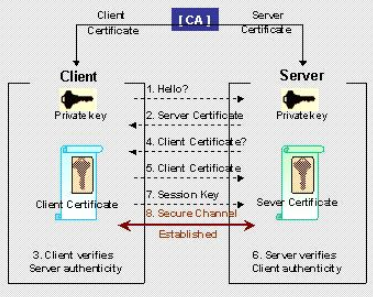
So between the routers participating in a VPN connection (for example R1 and R2).
R1 ------- Please send me your PUB Key ----- > R2
R1 <------ Please send me your PUB Key ------ R2
R1 and R2 get each other Public Key , they keep their private keys with themselves.
Anything encrypted by my
public keycan only be decrypted by the correspondingprivate key.
The problem here , is we do not know if the device requesting the Public Key is the realy device and not a masquerade attempt. This is where the CA comes in.
The function of a CA Server is to validate an identity. Its an authority that both R1 and R2 trust.
- You send you Public Key and your company documents to Verisign.
- Versign verifies and signs that for you and provides you the
X509certificate. - The other company who wants to talk to you , does the same.
So now both companies have their own certificates (ID-CERT).
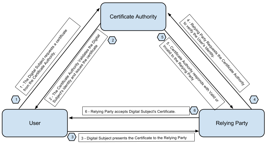
CA Server Based Setup
- Configure your CA Server
- Generate the Public/Private Key on the local device.
- Download the Root Certificate from the CA Server.
- Send/Enroll your public key with the CA Server
- CA Server validates your credentials and issues you an ID Cert.
The Entities Publick Key Info about the entitity CA Information Digital Signature of the CA Server
- The identity certificate is send back to the entity .
Certificate Relocation List : Checks for Certificates currency (How current it is)
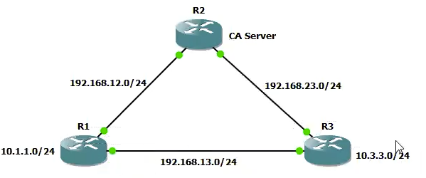
Step 1. CA Server Configuration
- Sync the Clock
clock timezone EST 4
clock set XX:XX:XX 29 Aug 2019
- Generate the RSA Key pair for the CA Server , this will be used for the root cert.
crypto key generate rsa modulus 1024 label IOSCA
- Configure your Router as a Web SERVER
ip http server
- Configure the CA Server Parameters
crypto pki server IOSCA
 database url flash:
 issuer-name CN=ABC CA Server O=ABC OU=Training L=Dubai C=IN
 grant auto
 no shut
Step 2. Client Configuration
- Sync the Clock
clock timezone EST 4
clock set XX:XX:XX 29 Aug 2019
- Generate the RSA Key pair for the CA Server , this will be used for the root cert.
crypto key generate rsa modulus 1024
- Configure your Router as a Web SERVER
ip domain-name devopsimplified.com
ip http server
- Create a pointer to the CA Server
crypto ca trustpoint TRUSPOINT enrollment url http://10.2.2.2:80 revocation-check none
- Download the root certificate from the CA Server
crypto ca authenticate TRUSTPOINT
- Enroll your public key with the CA Server and get a certificate issued. [ID Cert]
(On Client)# crypto ca enroll TRUSTPOINT
(client)# show crypto pki certificate
This concludes the PKI infrastructure configration on both the Server and the Client. In the next step we will confgure the VPN between the clients
CA Based VPNs
Step 3. IPSec LAN to LAN VPN using Certificates
! 1. Phase I
crypto isakmp policy 10
 auth rsa-sig ! This is changed for the crypto based on signatures
 hash md5
 enc 3des
 group 2

!2. Phase II

crypto ipsec transform-set TSET esp-3des esp-sha-hmac

!3. Interesting Traffic

acces-list 101 permit 10.1.1.0 0.0.0.255 10.3.3.0 0.0.0.255

!4. Crypto Map

crypto map CMAP 10 ipsec-isakmp
 match address 101
 set-peer 192.168.13.3
 set transform-set TSET

! 5. Apply to interface

int fa0/0
 crypto map CMAP
IKEv2 VPNS
What does IKEv2 bring to the table . IKEv2 is the replacemnt for ISAKMP which was also know as IKEv1 . IKEv2 pertains to the PHASE I only.
What does IKEv2 Bring to the table :
Scalability : Lets say in a Hub and Spoke type of VPN setup , multiple clients will could have different type of Phase I policy. On the Hub you would have to create multiple configuration to support all the Spokes.
IKEv2 allows scalability by usnign proposals which automatically expands to different combinations of Encryption , Integrity and Hash .
IKEv2 Proposal (Could use a combination of all the options below)
- Encrypt
3DES,AES - Integrity
MDS5,SHA - Group
2,5
Directional Pre-shared Keys : Allows the use of different preshared keys for the Phase I organisation. (Earlier the Pre-shared keys used to be same , in this case in each direction the key could be different)
More Secure Algorithms : More SHA variants availaible in IKEv2
IKEv2 VPN using legacy methods
R1 lo0 10.1.1.1

R2 lo0 10.2.2.2

R3 lo0 10.3.3.3
.
.
.
.
Here are the steps you need to configure :
PHASE I > PHASE II > ACL > MAP > APPLY TO INTERFACE
Everything starting Phase II remains same in IKEv2 based VPN , only changes is in the PHASE I
! R1
! 1. [A] Configure an IKEv2 Proposal
! Notice the different combinations available

crypto ikev2 proposal PROP-1
 integrity md5 sha256
 encryption 3des aes-cbc-192
 group 2 5  ! DH key algorothms

! 1. [B] Configure a policy and call the proposal

crypto ikev2 policy POLICY-1
 proposal PROP-1

! 1. [C] Configure and IKEv2 Key ring

crypto ikev2 keyring KR-1
 peer R2
  address 192.1.20.2
  pre-shared-key local cisco111   ! notice differen pre shared keys cisco111 and cisco 222
  pre-shared-key remore cisco222

! 1. [D] Configure an IKEv2 profile that will attach keyring to the authentication type. This will be attached to your crypto map.

crypto ikev2 profile IKEv2-PROF-1
 match identity remote address 192.1.20.2 255.255.255.255
 authentication local pre-share
 authentication remore pre-share
 keyring KR-1


! 2. PHASE II

crytp map transform-set ABC esp-rdes esp-md5-hmac

! 3. ACL

crypto ipsec 101 permit ip 10.1.1.0 0.0.0.255 10.2.2.0 0.0.0.255

!4. Crypto MAP

crypto map ABC 10 ipsec-isakmp
 match address 101
 set peer 192.1.20.2
 set transform-set ABC
 set ikev2-profile IKEv2-PROF-1


!5 . Apply the configuration

int fa0/0
 crypto map ABC
Repeat the above of the other side
show crypto ikev2 sa
IKEv2 VPN using S-VTIs (uses GRE tunnel and the routing on it)
R3
! R3
! 1. [A] Configure an IKEv2 Proposal
! Notice the different combinations available

crypto ikev2 proposal PROP-1
 integrity md5 sha1
 encryption 3des
 group 2 5  ! DH key algorothms

! 1. [B] Configure a policy and call the proposal

crypto ikev2 policy POLICY-1
 proposal PROP-1

! 1. [C] Configure and IKEv2 Key ring

crypto ikev2 keyring KR-1
 peer R4
  address 192.1.40.4
  pre-shared-key  cisco123   ! Common for local and remote


! 1. [D] Configure an IKEv2 profile that will attach keyring to the authentication type. This will be attached to your crypto map.

crypto ikev2 profile IKEv2-PROF-1
 match identity remote address 192.1.40.4 255.255.255.255
 authentication local pre-share
 authentication remote pre-share
 keyring KR-1

! 2. PHASE II

crytp map transform-set ABC esp-rdes esp-md5-hmac

! 3. IPSec Profile

crypto ipsec profile IPROF
 set transform-set TSET
 set ikev2 profile IKEv2-PROF-1

! 4. Tunnel Interface

interface tunnel0
 ip add 192.168.1.1 255.255.255.0
 tunnel source 192.1.30.3
 tunnel destination 192.1.40.4
 tunnel mode ipsec ipv4
 tunnel protection ipsec profile IPROF

! 5. Routing protocol

router eigrp 100
 no auto
 network 192.168.1.0
 network 10.0.0.0


!4. Crypto MAP

crypto map ABC 10 ipsec-isakmp
 match address 101
 set peer 192.1.20.2
 set transform-set ABC
 set ikev2-profile IKEv2-PROF-1


!5 . Apply the configuration

int fa0/0
 crypto map ABC
Repeat the above for R4
Flex VPN
Site to Site VPN [D-VTI / S-VTI based ]
FOUNDATION
In this example we are establisihisng a VPN tunnel between R1 and R2.
In a normal S-VTI (Static Virtual Tunnel Interface) you know the tunnel destination address. In this example the twist is that , what if the IP Address on R2’s e0/0 is dynamic ?
Here’s is what a typical tunnel interface configuration looks like :
! R2
interface tunnel 12
 ip add 192.168.12.1 255.255.255.0
 tunnel source e0/0
 tunnel destination 192.1.10.1  ! ### NOTICE
 tunnel mode ipsec ipv4
 tunnel protection ipsec profile IPROF-12
Notice the destination configuration (on R2) pointing to R1’s known and static address of e0/0. But what is R2’s e0/0 is dynamic ?
R1 would not be able to point the same way to R2 and R2 did.
To resolve this situation , we use (on R1) interface Virtual-template which has all the configuration as above interface but does not have the tunnel destination command.
Once R2 is assigned an IP Address on e0/0 by its ISP and tries to reach out to R1 , R1 gets to know the public IP Address of R2 and creates a Virtual Interface with the now known address as the destination address.
CONFIGURATION
R2
! 1. Phase I [IKEv2]

! A. Configure the Proposal

crypto ikev2 proposal PROP-1
 integrity md5 sha1
 encryption 3des
 group 2 5

! B. Configure the Policy

crypto ikev2 policy POL-1
 proposal PROP-1

! C. Configure the Keyring

crypto ikev2 keyring KR-12
 peer R1
  address 192.1.10.1
	pre-shared key cisco123

! D. Configure the IKEv2 Profile

crypto ikev2 profile PROF-12
 match identity remote address 192.1.10.1 255.255.255.255
 authentication local pre-share
 authentication remote pre-share
 keyring local KR-12

! 2. PHASE II

crypto ipsec transform-set TSET esp-3des esp-md5-hmac

! 3. Configure the IPSEC Profile

crypto ipsec profile IPROF-12
 set transform-set TSET
 set ikev2-profile PROF-12

! 4. Configure the Static Virtual Tunnel Interface [S-VTI]

interface tunnel 12
 ip add 192.168.12.1 255.255.255.0
 tunnel source e0/0
 tunnel destination 192.1.10.1
 tunnel mode ipsec ipv4
 tunnel protection ipsec profile IPROF-12

! 5. Configure the routing protocol

router eigrp 100
 no auto
 network 192.168.12.0
 network 10.0.0.0
R1
! 1. Phase I [IKEv2]

! A. Configure the Proposal

crypto ikev2 proposal PROP-1
 integrity md5 sha1
 encryption 3des
 group 2 5

! B. Configure the Policy

crypto ikev2 policy POL-1
 proposal PROP-1

! C. Configure the Keyring

crypto ikev2 keyring KR-12
 peer R2
  address 192.1.20.0 255.255.255.0 ! Here we know the subnet its coming from and not the actual IP , so we define the subnet its coming from. This has to be known.
	pre-shared key cisco123

! D. Configure the IKEv2 Profile

crypto ikev2 profile PROF-12
 match identity remote address 192.1.20.0 255.255.255.0  ! Here we know the subnet its coming from and not the actual IP , so we define the subnet its coming from. This has to be known.
 authentication local pre-share
 authentication remote pre-share
 keyring local KR-12
 virtual-template 12  !# Notice this , if somebody logs in with the PROF-12 , we would create a virtual tunnel interface.

! 2. PHASE II

crypto ipsec transform-set TSET esp-3des esp-md5-hmac

! 3. Configure the IPSEC Profile

crypto ipsec profile IPROF-12
 set transform-set TSET
 set ikev2-profile PROF-12

! 4. Configure the Virtual Tunnel Interface - Changes Step from the config above

int lo12
 ip address 192.168.12.1 255.255.255.0


interface virtual-template 12 type tunnel
 ip unnumbered lo12 ! Since in template you cannot assign a manuall address , you create loopback first and point it here .
 tunnel source e0/0
 !tunnel destination 192.1.10.1 !# This line is removed as we dont need this and is dynamically known when R2 tries to connect to us.
 tunnel mode ipsec ipv4
 tunnel protection ipsec profile IPROF-12

! 5. Configure the routing protocol

router eigrp 100
 no auto
 network 192.168.12.0
 network 10.0.0.0
 network 192.1.0.0 0.0.255.255
show interface virtual-access 1
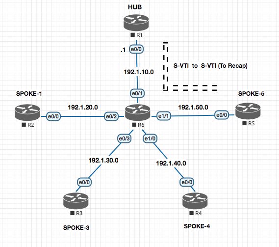
Static VTI to Static VTI Configuration
In this section we will configure the S-VTI between R1 and R5.
R1
! 1. Phase I [IKEv2]

! A. Configure the Proposal

crypto ikev2 proposal PROP-1
 integrity md5 sha1
 encryption 3des
 group 2 5

! B. Configure the Policy

crypto ikev2 policy POL-1
 proposal PROP-1

### Everything above is already configured from the section before , so no need to reconfigure it.

! C. Configure the Keyring

crypto ikev2 keyring KR-15
 peer R5
  address 192.1.50.5
	pre-shared key cisco123

! D. Configure the IKEv2 Profile

crypto ikev2 profile PROF-15
 match identity remote address 192.1.50.5 255.255.255.255
 authentication local pre-share
 authentication remote pre-share
 keyring local KR-15

! 2. PHASE II

crypto ipsec transform-set TSET esp-3des esp-md5-hmac

! 3. Configure the IPSEC Profile

crypto ipsec profile IPROF-15
 set transform-set TSET
 set ikev2-profile PROF-15

! 4. Configure the Static Virtual Tunnel Interface [S-VTI]

 interface tunnel 15
  ip add 192.168.15.1 255.255.255.0
  tunnel source e0/0
  tunnel destination 192.1.50.5
  tunnel mode ipsec ipv4
  tunnel protection ipsec profile IPROF-15

! 5. Configure the routing protocol

router eigrp 100
 no auto
 network 192.168.12.0
 network 192.168.15.0 ! New command
 network 10.0.0.0
 network 192.1.0.0 0.0.255.255
R5
! 1. Phase I [IKEv2]

! A. Configure the Proposal

crypto ikev2 proposal PROP-1
 integrity md5 sha1
 encryption 3des
 group 2 5

! B. Configure the Policy

crypto ikev2 policy POL-1
 proposal PROP-1

### Everything above is already configured from the section before , so no need to reconfigure it.

! C. Configure the Keyring

crypto ikev2 keyring KR-15
 peer R1
  address 192.1.10.1
	pre-shared key cisco123

! D. Configure the IKEv2 Profile

crypto ikev2 profile PROF-15
 match identity remote address 192.1.10.1 255.255.255.255
 authentication local pre-share
 authentication remote pre-share
 keyring local KR-15

! 2. PHASE II

crypto ipsec transform-set TSET esp-3des esp-md5-hmac

! 3. Configure the IPSEC Profile

crypto ipsec profile IPROF-15
 set transform-set TSET
 set ikev2-profile PROF-15

! 4. Configure the Static Virtual Tunnel Interface [S-VTI]

 interface tunnel 15
  ip add 192.168.15.5 255.255.255.0
  tunnel source e0/0
  tunnel destination 192.1.10.1
  tunnel mode ipsec ipv4
  tunnel protection ipsec profile IPROF-15

! 5. Configure the routing protocol

router eigrp 100
 no auto
 network 192.168.12.0
 network 192.168.15.0 ! New command
 network 10.0.0.0
 network 192.1.0.0 0.0.255.255
Spoked to Spoke FLEX VPN
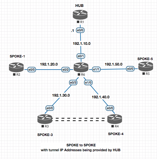
Here we will setup a Flex VPN between SPOKE-3 and SPOKE-4 with R1 acting as the HUB.
HUB SIDE CONFIGURATION
! R1 - HUB

! 1. Configure the AAA and policies required to propagate IP Address to the tunnel interfaces on the client.

aaa new-model
aaa authorization network default local
!
ip local pool DHCP_POOL_FLEX 192.168.134.5 192.168.134.254
!
crypto ikev2 authorization policy NHRP
 pool DHCP_POOL_FLEX
 route set interface ! Injects the route pointing to the DHCP Server (myself) in the client.

! PHASE I
! A. Configure the Proposal

crypto ikev2 proposal PROP-1
 integrity md5 sha1
 encryption 3des
 group 2 5

! B. Configure the Policy

crypto ikev2 policy POL-1
 proposal PROP-1

### Everything above is already configured from the section before , so no need to reconfigure it.

! C. Configure the Keyring

 crypto ikev2 keyring KR-134
  peer 34 ! Anthing here as we do not have a specific
   address 0.0.0.0 ! Could be many addresses so a wild card .
 	pre-shared key cisco123

 ! D. Configure the IKEv2 Profile

crypto ikev2 profile PROF-134
 match identity remote address 0.0.0.0 0.0.0.0  ! Could be many addresses so a wild card .
 authentication local pre-share
 authentication remote pre-share
 keyring local KR-134
 virtual-template 134
 aaa authorization group psk list NHRP NHRP ! Link the auth policy created above


! 3. PHASE II

! crypto ipsec transform-set TSET esp-3des esp-md5-hmac  ! This command is ommiteed as it is already there from the prev section.

! 4. Configure the IPSec Profile

crypto ipsec profile IPROF-134
 set transform-set TSET
 set ikev2-profile PROF-134


! 5.  Configure a Virtual-template interface. [NHRP Interface]

interface loopback 134
 ip address 192.168.134.1 255.255.255.0
!
interface virtual-template 134 type tunnel
 ip unnumbered loopback 134
 tunnel source e0/0
 ip nhrp network-id 134
 ip nhrp redirect
SPOKE SIDE CONFIGURATION
! R3 - SPOKE

! 1. Configure the AAA and policies required to propagate IP Address to the tunnel interfaces on the client.

aaa new-model
aaa authorization network default local
!

crypto ikev2 authorization policy NHRP
 route set interface ! Injects the route pointing to the DHCP Server (myself) in the client.

! PHASE I
! A. Configure the Proposal

crypto ikev2 proposal PROP-1
 integrity md5 sha1
 encryption 3des
 group 2 5

! B. Configure the Policy

crypto ikev2 policy POL-1
 proposal PROP-1

### Everything above is already configured from the section before , so no need to reconfigure it.

! C. Configure the Keyring

 crypto ikev2 keyring KR-134
  peer 34 ! Anthing here as we do not have a specific
   address 0.0.0.0 ! Could be many addresses so a wild card .
 	pre-shared key cisco123

 ! D. Configure the IKEv2 Profile

crypto ikev2 profile PROF-134
 match identity remote address 0.0.0.0 0.0.0.0  ! Could be many addresses so a wild card .
 authentication local pre-share
 authentication remote pre-share
 keyring local KR-134
 virtual-template 134
 aaa authorization group psk list NHRP NHRP ! Link the auth policy created above


! 3. PHASE II

crypto ipsec transform-set TSET esp-3des esp-md5-hmac  ! This command is ommiteed as it is already there from the prev section.

! 4. Configure the IPSec Profile

crypto ipsec profile IPROF-134
 set transform-set TSET
 set ikev2-profile PROF-134


! 5.  Configure a Virtual-template interface. [NHRP Interface]

!#######################################################################
!#### This interface is the tunnel interface between R3 and R1
!######################################################################
interface Tunnel134
 ip address negotiated ! #### Gets from the DHCP Pool from R1
 tunnel source e0/0
 tunnel destination 192.1.10.1
 ip nhrp network-id 134
 ip nhrp shortcut virtual-template 134
 tunnel protection ipsec profile IPROF-134
!

!#######################################################################
!#### This is what would create the Spoke to Spoke Virtual Access link between R3 and R4
!#######################################################################
interface virtual-template 134 type tunnel
 ip unnumbered tunnel 134
 tunnel source e0/0
 ip nhrp network-id 134
 ip nhrp shortcut virtual-template 134
 tunnel protection ipsec profile IPROF-134

router eigrp
 no auto
 network 192.168.134.0
R4 No changes required from R3 .
! R4 - SPOKE

! 1. Configure the AAA and policies required to propagate IP Address to the tunnel interfaces on the client.

aaa new-model
aaa authorization network default local
!

crypto ikev2 authorization policy NHRP
 route set interface ! Injects the route pointing to the DHCP Server (myself) in the client.

! PHASE I
! A. Configure the Proposal

crypto ikev2 proposal PROP-1
 integrity md5 sha1
 encryption 3des
 group 2 5

! B. Configure the Policy

crypto ikev2 policy POL-1
 proposal PROP-1

### Everything above is already configured from the section before , so no need to reconfigure it.

! C. Configure the Keyring

 crypto ikev2 keyring KR-134
  peer 34 ! Anthing here as we do not have a specific
   address 0.0.0.0 ! Could be many addresses so a wild card .
 	pre-shared key cisco123

 ! D. Configure the IKEv2 Profile

crypto ikev2 profile PROF-134
 match identity remote address 0.0.0.0 0.0.0.0  ! Could be many addresses so a wild card .
 authentication local pre-share
 authentication remote pre-share
 keyring local KR-134
 virtual-template 134
 aaa authorization group psk list NHRP NHRP ! Link the auth policy created above


! 3. PHASE II

crypto ipsec transform-set TSET esp-3des esp-md5-hmac  ! This command is ommiteed as it is already there from the prev section.

! 4. Configure the IPSec Profile

crypto ipsec profile IPROF-134
 set transform-set TSET
 set ikev2-profile PROF-134


! 5.  Configure a Virtual-template interface. [NHRP Interface]

!#######################################################################
!#### This interface is the tunnel interface between R3 and R1
!######################################################################
interface Tunnel134
 ip address negotiated ! #### Gets from the DHCP Pool from R1
 tunnel source e0/0
 tunnel destination 192.1.10.1
 ip nhrp network-id 134
 ip nhrp shortcut virtual-template 134
 tunnel protection ipsec profile IPROF-134
!

!#######################################################################
!#### This is what would create the Spoke to Spoke Virtual Access link between R3 and R4
!#######################################################################
interface virtual-template 134 type tunnel
 ip unnumbered tunnel 134
 tunnel source e0/0
 ip nhrp network-id 134
 ip nhrp shortcut virtual-template 134
 tunnel protection ipsec profile IPROF-134

router eigrp
 no auto
 network 192.168.134.0
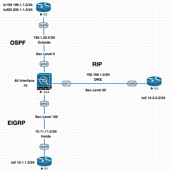
ASA Firewalls
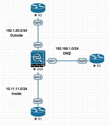
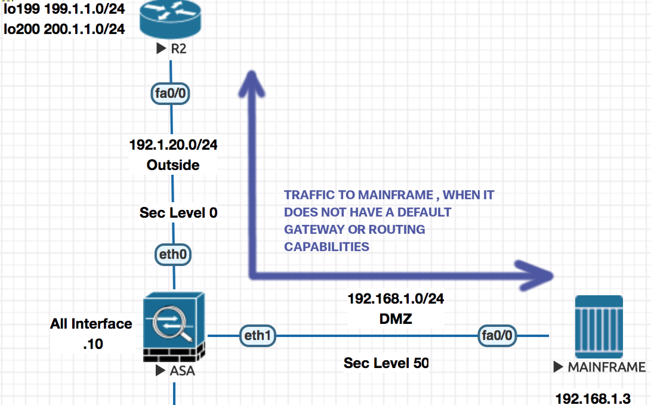
ASA is technicaly a router acting as a firewall. Outside is your external network , Inside is your internal network and DMZ is things like your email , web and DNS Server.
ASA though is a router , it has some different charecteristc. Traffic from one interface one iterface to other is allowed by default on a router. On an ASA though it does not allow all traffic to traverese through it.
-
Traffic flow through the firewalls is controlled by the Security Levels fof the interface. By default the security level of the interface is set to 0.
Name of the interfaceis a required parameter along with theSecurity level.-
If you name the interface
inside, the security level is set to100. Traffic moving from Higher security level to Lower is allowed by default. Low to High is blocked. (Default charecteristc) . Any other name on a blank interface set the security level to 0. -
Traffic between same security level , the communication would not happen AT ALL (even after creatign exceptions). Now this behaviour can be changed by
same-security-traffic permit inter-interfacewhich allows all communication between the same security levels . -
For traffic goign from high to low , the traffic will go through. NOTE: By default only TCP/IP is inspected , which means outgoign traffic will be allowed to go out and come in. Everythign else (Apart from TCP/IP) is not inspected by default , hence can go out but not come in.
- ASA only blocks THRU traffic , traffic coming TO firewall is allowed. The only reason you are allowed to PING is becuase the ICMP feature is enabled by default.
- Firewall does not allow Telnet on a Level 0 interface. It has to be specificcaly allowed based on source.
- If a connection is allowed
into an ASA, then it will automatically be allowedout, as ASAs are stateful. This means you do not need to write aninand anoutACL, just anin.
Interface Configuration
To default an interface .
clear configure interface gi0
Shows the active connections
ciscoasa# show conn
1 in use, 1 most used
TCP Outside  192.1.20.2:23 inside  10.11.11.1:56358, idle 0:00:09, bytes 184, flags UIO
Typical Access List
access-list ABC permit tcp host 192.1.20.2 10.11.11.0 255.255.255.0 eq telnet
access-group ABC in interface outside ! IN denotes the direction , outside is the interface on which it is applied.
To disable TO traffic to the interface of the firewall :
icmp deny any outside
To allow Internal to ping out :
icmp permit any echo-reply outside
Allow on single endpoint [192.1.20.2] to ping from Outside :
icmp permit host 192.1.20.2 echo outside
To enable ssh
crypto key generate rsa modulus 1024
username admin pass cisco123
aaa authentication ssh console LOCAL !Local Authentication
Routing Configuration
Checking routes on a ASA
ciscoasa# show route

Codes: C - connected, S - static, I - IGRP, R - RIP, M - mobile, B - BGP
       D - EIGRP, EX - EIGRP external, O - OSPF, IA - OSPF inter area
       N1 - OSPF NSSA external type 1, N2 - OSPF NSSA external type 2
       E1 - OSPF external type 1, E2 - OSPF external type 2, E - EGP
       i - IS-IS, L1 - IS-IS level-1, L2 - IS-IS level-2, ia - IS-IS inter area
       * - candidate default, U - per-user static route, o - ODR
       P - periodic downloaded static route

Gateway of last resort is not set

C    192.1.20.0 255.255.255.0 is directly connected, Outside
D    10.1.1.0 255.255.255.0 [90/156160] via 10.11.11.1, 0:00:12, inside
C    10.11.11.0 255.255.255.0 is directly connected, inside
C    192.168.1.0 255.255.255.0 is directly connected, DMZ
Example of EIGRP Authentication on a Router
key chain KEY_CHAIN
 key 1
  key-string cisco123
!
interface f0/0
 ip authentication mode eigrp 100 md5
 ip authentication key-chain eigrp 100 KEY_CHAIN
!
Example of EIGRP Authentication on a ASA
interface eth2
 authentication mode eigrp 100 md5
 authentication key eigrp 100 cisco123 key-id 1
!
Example RIP Configuration on Router and ASA
! R3
router rip
 version 2
 no auto
 network 192.168.1.0
 network 10.0.0.0

! ASA
router rip
 version 2
 no auto
 network 192.168.1.0
 network 10.0.0.0
Example of RIP Authentication on a Router and a ASA
! R3
key chain KEY_CHAIN
 key 1
  key-string cisco123
!
interface f0/0
 ip rip authentication mode  md5
 ip rip authentication key-chain KEY_CHAIN

! ASA
interface eth1
 rip authentication mode md5
 rip authentication key cisco123 key_id 1
!
Example OSPF Configuration on Router and ASA
! R2
router ospf 1
 network 192.1.20.0 0.0.0.255 area 0
 network 199.1.1.0 0.0.0.255 area 0
 network 200.1.1.0 0.0.0.255 area 0


! ASA
router ospf 1
 network 192.1.20.0 0.0.0.255 area 0
 network 199.1.1.0 0.0.0.255 area 0
 network 200.1.1.0 0.0.0.255 area 0
Example of OSPF Authentication on a Router and a ASA
! R2
key chain KEY_CHAIN
 key 1
  key-string cisco123
!
interface f0/0
 ip ospf authentication message-digest
 ip ospf message-digest-key 1 md5 cisco123
!
! ASA
interface f0/0
 ip ospf authentication message-digest
 ip ospf message-digest-key 1 md5 cisco123
!
Redistribution
router rip
 redistribute ospf 1 metric 1
 redistribute eigrp 100 metric 1

router eigrp 100
 redistribute rip metric 1 1 1 1 1
 redistribute ospf 1 metric 1 1 1 1 1

router ospf 1
 redistribute rip metric 30 subnets
 redistribute eigrp 100 metric 30 subnets
NAT
Good Link https://www.practicalnetworking.net/stand-alone/cisco-asa-nat/#asa-identity-nat
FOUNDATION
Source NAT If my internal address is gettign translated, regardless if the direction of the access, it is called Source NAT. Basicall if MY address is getting translated its Source NAT.
Destiation NAT If the External Address / Remote Address / Foreign Addresss changes , it is called Destination NAT . The word destination is “THEM” .
99% of the time you are doing Source NAT .
Source Dynamic NAT Allows internal users to go out using Public address from a pool defined on the firewall. Also know as Object NAT or Auto NAT (In the picture above , its traffic goign from R1 to R2 being natted at ASA)
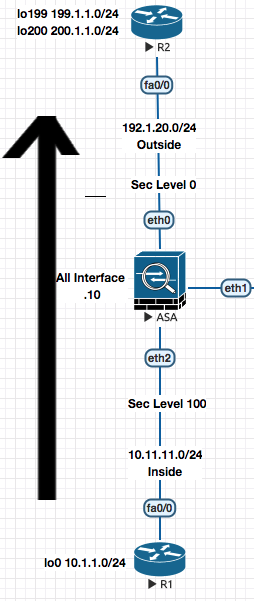
It is called Dynamic becuase its on need basis when traffic arrives at the ASA
########## Source Dynamic NAT Configuration Example #############

! 1. Define the pool

object network POOL1 ! Pool of externally reachable IP Addresses.
 range 192.1.20.101 192.1.20.200

! 2. Specify the address that can use the pool

object network INS-NET
 subnet 10.11.11.0 255.255.255.0
 nat (inside,outside) dynamic POOL1
 ! This is where I link the POOL , saying traffic going from
 ! inside to outside should be dynamically natted using the pool POOL1
To check the trhasnaltions of NAT table .
show xlate
Source Static NAT
Translates an internal address on the outside. This is done staticaly so that an entry is created on trnaslation table.
You still need to allow the accesss from Low to High. Access list needs to be created.
In contrast to the above Dynamic Source Nat configuration , what about the traffic coming from the internet to the the DMZ . Email , Web Servers need a static IP to be bound to so that people can reach them.
This is where we would need Static NAT
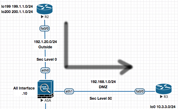 Example of Nat’ing the Web Server in DMZ
! Creation of NAT Entry
object network WWW1
 host 192.168.1.11 ! Address of Web Server in DMZ
 nat (dmz, outside) static 192.1.20.21
 ! Means , translation of DMZ address to Ourside address of 192.1.20.21
! Creation of Access list
access-list OUTSIDE permit tcp any host 192.168.1.11 eq 80
access-list OUTSIDE permit tcp any host 192.168.1.11 eq 80
!
access-group OUTSIDE in interface outside
Note:
1. Most of the time 99%, the flow looks like above , the traffic from the inside (
RED) is connfigured first and then the the outside direction (BLUE). 2. Also most of the time 99% , the first interface is higher security level (RED) and next is the lower security level (BLUE).
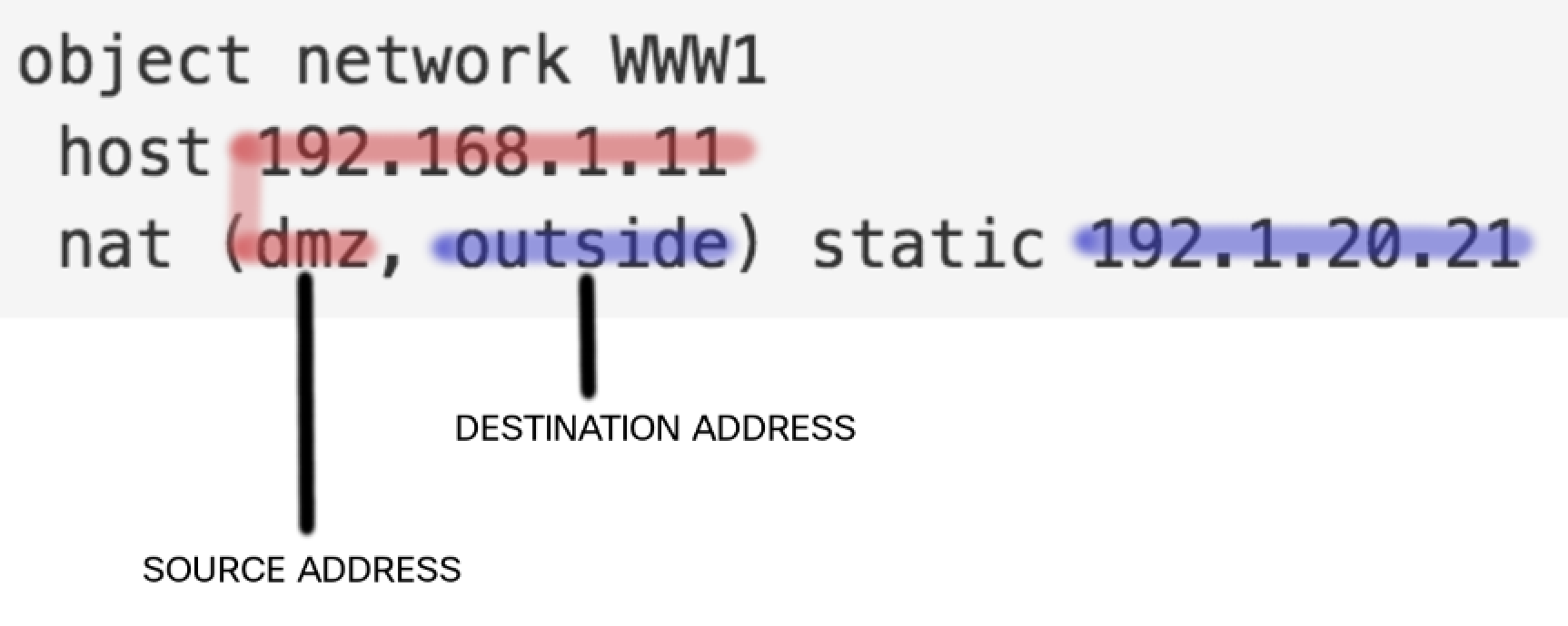
REDworks on Source Address ,BLUEworks on Destination Address So lets say in the traffic example above , where traffic is coming from the outside to the DMZ :
Step 1. Packet comes fromt he internet
199.1.1.1to192.1.20.21and arrives on theOUTSIDEinterface. Step 2. SinceOUTSIDElooks at/ works on at the destination address of the packet (look at the mapping in the picture) and matches the configured address192.1.20.21it changes the destination address from192.1.20.21to192.168.1.11. Now the packet looks likeSrc 199.1.1.1 --> Dst 192.168.1.11Step 3. Next the Web Server at192.168.1.11responds back with source as192.168.1.11and destination as199.1.1.1, this arrives on the DMZ interface. SinceDMZin this case looks at the Source Address , it changes the source address from 192.168.1.11 to 192.1.20.21 and send the packet back on the internet.Src 192.1.20.21 --> Dst 199.1.1.1
Dynamic PAT
Now since all the above examples of NAT a one to one mappng between extenral and internal address is done. It wastes a lot of public addresses and is not efficient. Hence PAT is considered here.
Two Options
- Using the Outside Interface
object network INS-NET
 subnet 10.11.11.0 255.255.255.0
 nat (inside,outside) dynamic interface
- Using an IP Address
A. Create an IP Address or Pool of IPs

object network POOL-A
 host 192.1.20.5

B. Create the Inside Network and specify to use the Pool for the PAT

object network INS-NET
 subnet 10.11.11.0 255.255.255.0
 nat (ins,out) dynamic pat-pool POOL-A
Static PAT - For Public Facing Servers
object network WWW1
 host 192.168.1.11
 nat (dmz,outside) static 192.1.20.11 service tcp 80 80
!
object network EMAIL1
 host 192.168.1.12
 nat (dmz,outside) static 192.1.20.11 service tcp 25 25
!
object network DNS1
 host 192.168.1.12
 nat (dmz,outside) static 192.1.20.11 service tcp 53 53
!
!
object network R3
 host 192.168.1.3
 nat (dmz,outside) static 192.1.20.11 service tcp 23 2311
 ! Traffic coming on 192.1.20.11 on port 2311
 ! should get translated to 192.168.1.3 port 23
Example
Traffic coming on 192.1.20.11 on port 2311 (from
outside) should get translated to 192.168.1.3 port 23 (in thedmz)
Twice NAT
This allows you to change the Source as well as the detination in a single NAT statement. This is also known as the Manual-NAT.
- Create Object for all the addresses involved.
object network R3-D ! Address of Mainfram in the DMZ
 host 192.168.1.3
object network R3-O ! Address on Mainframe on Outside
 host 192.1.20.20
!
object network H199-O ! Address of the internet host.
 host 199.1.1.1
object network H199-D
 host 192.168.1.79
- Create the Twice-Nat/Manual-NAT statement.
nat source static R3-D R3-O destination static destination static H199-D H199-O
!
! nat (dmz,outside) source static R3-D R3-O destination static destination static H199-D H199-O
! You could do it like above (dmz,inside) to lock down to the interface level.
The above line means that If the packet is going from R3-D to H199-D , change R3-D to R3-O and change H199-D H199-O
Transparent Firewall
Notice the same IP Subnet 192.1.10.0 is divided in two VLANs (10, 20)
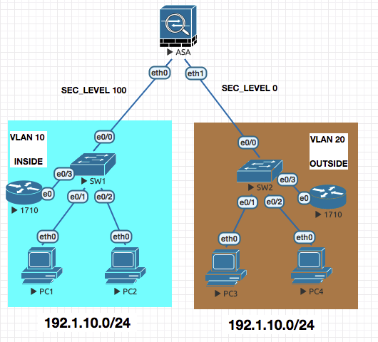
CONFIGURATION
- Configuring the firewall as transparent
firewall transparent
- Configure the interface to be part of the same Bridge-group
interface e0
 nameif inside
 security-level 100
 bridge-group 5
 no shut

interface e1
 nameif outside
 security-level 0
 bridge-group 5
 no shut
- Enable the IP Address on bridge group to forward traffic
interface bvi 5
 ip address 192.1.10.10
Once the above is done , everthing else is managed as the standard firewall.
acces-list OUTSIDE permit tcp host 192.1.10.3 host 192.1.10.1 eq telnet
access-group OUTSIDE in interface inside/outside
Ethertype ACLs
access-list ABC ethertype permit 0x2133
access-group ABC permit in
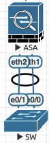
ASA Redundancy
Redundant Interfaces (Failover , Only one active)
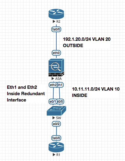
ciscoasa# show running-config interface redundant 1
!
interface Redundant1
 member-interface Ethernet1
 member-interface Ethernet2
 nameif inside
 security-level 100
 ip address 10.11.11.10 255.255.255.0
ciscoasa#

ciscoasa# show interface Redundant 1
Interface Redundant1 "inside", is up, line protocol is up
  Hardware is i82559, BW 100 Mbps, DLY 100 usec
	Auto-Duplex(Full-duplex), Auto-Speed(100 Mbps)
	Input flow control is unsupported, output flow control is unsupported
	MAC address 5000.0002.0001, MTU 1500
  Redundancy Information:
	Member Ethernet1(Active), Ethernet2
	Last switchover at 01:23:14 UTC Jul 6 2018
Redundant Interfaces (Port Channel , both interfaces active)
! SW
!
interface Port-channel10
 switchport access vlan 10
 switchport mode access
!
interface range e0/1 - 1
 channel-group 10 mode active
!
! ASA
interface e1
 channel-group 10 mode active
interface e2
 channel-group 10 mode active
interface port-channel 10
 nameif inside
 ip address 10.11.11.10 255.255.255.0
 no shut
!
Security Contexts [Virtual Firewalls]
mode multiple ! Requires a reboot

show mode

show context

! Unshut all the interfaces

int eth0
 no shut
int eth1
 no shut
int eth2
 no shut

context admin
 allocate-interface Management0/0

context SALES
 allocate-interface gig0/0
 allocate-interface gig0/1
 config-url flash:SALES.cfg

context FINANCE
 allocate-interface gig0/2
 allocate-interface gig0/3
 config-url flash:FINANCE.cfg

changeto context SALES  ! And after this NORMAL Configuration

admin-context SALES ! Will change the SALES context as admin context.
! You can change from Admin context to system context
changeto context
You can also define the amount of resources a particular context gets by the use of Class
! Class Creation and Limitation configuration
class CLASS_GOLD
 limit-resource conns 100000 ! A Zero means no limit
 limit-resource xlate 5000
class CLASS_SILVER
 limit-resource conns 1000
 limit-resource xlate 1000

! Applying the Class on the Context
context FINANCE
 member CLASS_SILVER
context SALES
 member CLASS_GOLD
ciscoasa(config)# class GOLD
ciscoasa(config-class)# limit-resource ?
class mode commands/options:
  rate           Enter this keyword to specify a rate/sec
Following resources available:
  ASDM           ASDM Connections
  All            All Resources
  Conns          Connections
  Hosts          Hosts
  Mac-addresses  MAC Address table entries
  Routes         Routing Table Entries
  SSH            SSH Sessions
  Telnet         Telnet Sessions
  VPN            VPN resources
  Xlates         XLATE Objects
You can have subinterfaces from a the same interface part of 2 different virtual contexts.
Failover
Failover is redundancy at the device level .
Active / Standby (Stateless)
Active - The box which is in the forwarding mode. All configurations are done on the Active Box .
Standby - The box that is not forwarding but has all the configurations limited .
The active box will respond to the ARP request from the clients
Primary - Secondary is defined in configuration. When the ASA pair boots for the firt time the ASA defines as Primary becomes Active and the one defined as Secondary becomes Standby.
The definition of Primary/Seconday does not change in case of falilue. These are Roles. During failover the device moves from Active to Standby and vice versa.
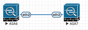
! ACTIVE  ASA6
failover lan interface FAILOVER eth2
failover interface ip FAILOVER 10.100.100.1 255.255.255.0 standby 10.100.100.2
! The first IP is for ACTIVE and the second for STANDBY.
failover lan unit primary
failover key cisco123 ! For securing communication
failover
!
! STANDBY ASA7
failover lan interface FAILOVER eth2
failover interface ip FAILOVER 10.100.100.1 255.255.255.0 standby 10.100.100.2
failover lan unit secondary
failover key cisco123
failover
!
The one configured above is a Stateless failover , where the end user isnt replicated for both the firewalls
ASA7(config)# ..

	Detected an Active mate
Beginning configuration replication from mate.
ERROR: Password recovery was not changed, unable to access
the configuration register.
Crashinfo is NOT enabled on Full Distribution Environment
End configuration replication from mate.
To display the current state of ASA in CLI use
prompt hostname state
The one configured above is a Stateless failover , where the end user isnt replicated for both the firewalls , with that we move into the next topic of Active/Standby with Statefull firewalls
Active / Standby (Statefull)
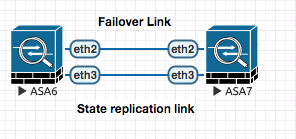
To configure active active failover for ASA , you have to configure another failover link :
! Using separate link for Active/Active config
interface eth3
failover link Stateful_Failover eth3
failover interface ip Stateful_Failover 10.200.200.1 255.255.255.0 standby 10.200.200.2
!
OR use the same link used for active/standby config .
ASA6(config)# failover link FAILOVER eth2
Active / Active (Statefull)
In active/active failover , one of each context is ACTIVE in different ASA and the other is PASSIVE.
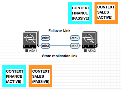
In case of a box failure , the Active Context on the failed box will move to the other active ASA.
! ASA1
failover lan interface FAILOVER eth2
failover interface ip FAILOVER 10.100.100.1 255.255.255.0 standby 10.100.100.2
failover lan unit primary
failover key cisco123
!
failover group 1
 preempt
 primary
failover group 2
 preempt
 secondary
!
context SALES
 join-failover-group 1 ! Making Sales active on Primary
!
context FINANCE
 join-failover-group 2 ! Making Finance active on Secondary
!
failover link FAILOVER eth2 ! for active state replication .
!
failover
! ASA2
failover lan interface FAILOVER eth2
failover interface ip FAILOVER 10.100.100.1 255.255.255.0 standby 10.100.100.2
failover lan unit secondary
failover key cisco123
!
failover
wr mem all ! Saves all config
ASA VPN Configuration (NAT-T)
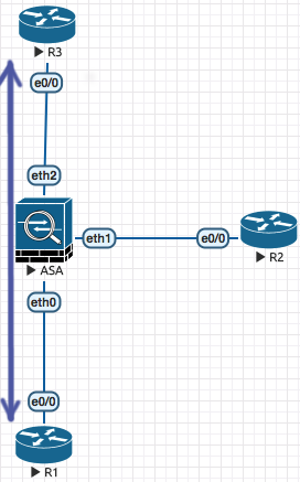
An example of a VPN tunnel traversin the Firewall
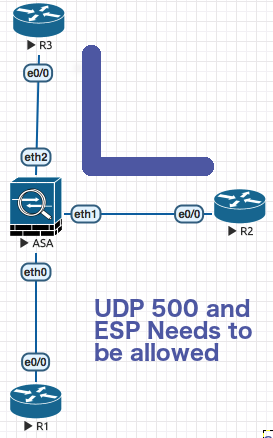
In the above picture R3 and R2 are establishing VPN tunnel in the standard way pointing to each other peer ip address which is directly reachable on the internet without the need of NAT .
UDP 500 (ISAKMP) and ESP Traffic needs to be permiited through the firewall . like following :
access-list OUTSIDE permit udp host x.x.x.x host x.x.x.x eq 500
access-list OUTSIDE permit esp host x.x.x.x host x.x.x.x

access-group OUTSIDE in interface outside
Now above configuration is OK , but what if you have to establish VPN between R1 which has a non publically routable IP and R3 ?
 In this case you basically will map a Public IP Address to R1’s address.
So R3 points to the publically NAT’ed IP of R1 and R1 points directly to R3.
In this case you basically will map a Public IP Address to R1’s address.
So R3 points to the publically NAT’ed IP of R1 and R1 points directly to R3.
Routers have a special charesctersistic called NAT Detection , this is an inbuilt feature of IPSEC which always takes place . This is basically becuase in the intial negotiation the ipsec devices send their local ip to the remote ipsec endpoint. THe remote endpoint can then do the necessary accomodation as per NAT-T .
In this case on the ASA you have to allow IPSEC and ESP
access-list OUTSIDE permit udp host x.x.x.x host x.x.x.x eq 500
access-list OUTSIDE permit esp host x.x.x.x host x.x.x.x eq 4500
!
access-group OUTSIDE in interface outside
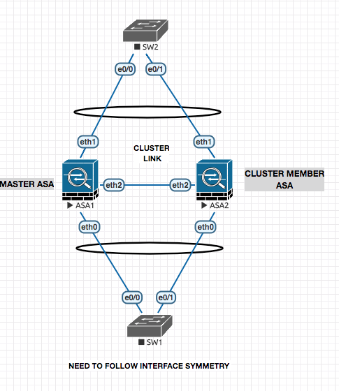
Clustering
Combining the multiple firewalls together to make a more powerfull version. 8 to 16 Boxes can be part of the cluster dependign ont he software level.
Spanned Mode
! ASA 1
! 1. Set the Cluster Mode
cluster interface-mode spanned force
! 2. Configure the Cluster Configuration
cluster group CCIESECv5
 local-unit PRI
 cluster-interface eth2 ip 10.100.100.1 255.255.255.0
 priority 1
 key cisco123
 enable noconfirm

! ASA 2
! 1. Set the Cluster Mode
cluster interface-mode spanned force
! 2. Configure the Cluster Configuration
cluster group CCIESECv5
 local-unit SEC
 cluster-interface eth2 ip 10.100.100.2 255.255.255.0
 priority 2
 key cisco123
 enable noconfirm

#######################################################

ciscoasa(cfg-cluster)# show cluster info
Cluster CCIESECv5: On
    Interface mode: spanned
    This is "PRI" in state MASTER
        ID        : 0
        Version   : 9.1(5)16
        Serial No.: JMX1203L0NN
        CCL IP    : 10.100.100.1
        CCL MAC   : 5000.0002.0002
        Last join : 21:59:37 UTC Jul 12 2018
        Last leave: N/A
Other members in the cluster:
    Unit "SEC" in state SLAVE_BULK_SYNC
        ID        : 1
        Version   : 9.1(5)16
        Serial No.: JMX1203L0NN
        CCL IP    : 10.100.100.2
        CCL MAC   : 5000.0001.0002
        Last join : 21:59:57 UTC Jul 12 2018
        Last leave: N/A
Configuring the port channel ont he ASAs now :
Now the configuration below , thouh will be done on the master will configured the same (replicated) on the other ASAs as well.
!
interface eth1
 channel-group 10 mode active
 no shut
!
interface port-channel 10
 port-channel span-cluster ! Tell that the port is a part of a spanned configuration
 nameif inside
 ip address 10.11.11.10 255.255.255.0
 no shut
!
Individual Interface Mode
The this mode , the ports are not in a port channel and are Individual interfaces with IP address configured to them via the Master ASA.
The Routers do the logic of Equal Cost Load Balancing to send the traffic IN or OUT side to the ASA as they peer with the ASA as EIGRP.
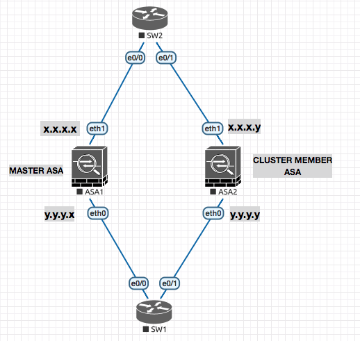
ip local pool OUTSIDE 192.1.20.11 - 192.1.20.15

interface eth1
 nameif outside
 ip address 192.1.20.10 255.255.255.0 cluster-pool OUTSIDE
 ! Set .10 as the eth1 ip and get the IP for others from the pool to set.
IKEv1 Site-to-Site on ASA (ASA to Router)
In this example we will be setting up the VPN tunnel between a IOS Router R3 and ASA ASA-1
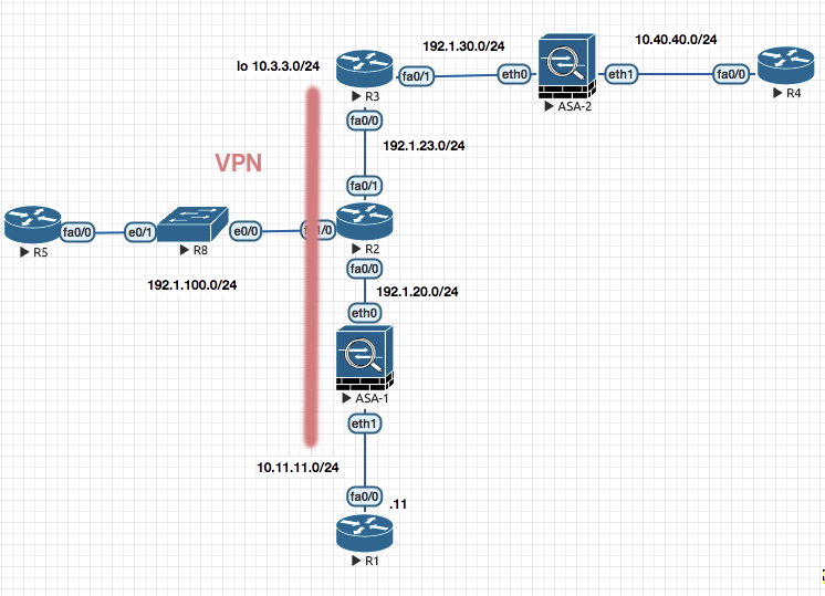
R3
! R3
! 1. PHASE 1
crypto isakmp policy 10
 auth pre-share
 encryption 3des
 hash sha
 group 2
!
crypto isakmp key cisco123 address 192.1.20.1

! 2. Phase II

crypto ipsec transform-set TSET esp-aes esp-sha-hmac

! 3. ACL

! Define interesting traffic ; Routers have inverse mark
access-list 101 permit ip 10.3.3.0 0.0.0.255 10.11.11.0 0.0.0.255

! 4. Crypto MAP

crypto map CMAP 10 ipsec-isakmp
 match address 101
 set peer 192.1.20.1
 set transform-set TSET

! 5. Apply to the outgoing interface

interface f0/0
 crypto map CMAP
ASA-1 (Output from vpnsetup Command and modifications)
1. Configure ISAKMP policy

! Change isakmp to ikev1
crypto ikev1 policy 10
 authentication pre-share
 encryption 3des
 hash sha
 group 2 ! Required in ikev1

2. Configure transform-set

crypto ipsec transform-set TSET esp-aes esp-sha-hmac

3. Configure ACL

access-list 101  permit ip 10.11.11.0 255.255.255.0 10.3.3.0 255.255.255.0

4. Configure Tunnel group

tunnel-group 192.1.23.3 type ipsec-l2l
tunnel-group 192.1.23.3 ipsec-attributes
 ikev1 pre-shared-key cisco123 ! Added `ikev1` here .

5. Configure crypto map and attach to interface

crypto map mymap 10 match address 101
crypto map mymap 10 set peer 192.1.23.3
crypto map mymap 10 set transform-set TSET
!crypto map mymap 10 set reverse-route
crypto map mymap interface outside

6. Enable isakmp on interface

crypto  ikev1 enable outside
! Change isakmp to ikev1
IKEv2 Site-to-Site (Between ASA and IOS)
R5 (R5 towards ASA)
! R5
! 1. [A] Configure an IKEv2 Proposal
! Notice the different combinations available

crypto ikev2 proposal PROP-1
 integrity md5 sha256
 encryption 3des aes-cbc-192
 group 2 5  ! DH key algorothms

! 1. [B] Configure a policy and call the proposal

crypto ikev2 policy POLICY-1
 proposal PROP-1

! 1. [C] Configure and IKEv2 Key ring

crypto ikev2 keyring KR-1
 peer R2
  address 192.1.20.2
  pre-shared-key local cisco111   ! notice differen pre shared keys cisco111 and cisco 222
  pre-shared-key remore cisco222

! 1. [D] Configure an IKEv2 profile that will attach keyring to the authentication type. This will be attached to your crypto map.

crypto ikev2 profile IKEv2-PROF-1
 match identity remote address 192.1.20.2 255.255.255.255
 authentication local pre-share
 authentication remore pre-share
 keyring KR-1


! 2. PHASE II

crytp map transform-set ABC esp-rdes esp-md5-hmac

! 3. ACL

crypto ipsec 101 permit ip 10.1.1.0 0.0.0.255 10.2.2.0 0.0.0.255

!4. Crypto MAP

crypto map ABC 10 ipsec-isakmp
 match address 101
 set peer 192.1.20.2
 set transform-set ABC
 set ikev2-profile IKEv2-PROF-1


!5 . Apply the configuration

int fa0/0
 crypto map ABC
ASA-2 (ASA towards R5)
1. Configure ISAKMP policy

! Change isakmp to ikev2
crypto ikev2 policy 10
 integrity md5 sha256
 encryption 3des aes-cbc-192
 group 2 5  ! DH key algorothms

2. Configure transform-set

crypto ipsec ikev2 ipsec-proposal PROP-1
 protocol esp encryption 3des
 integrity md5

3. Configure ACL

access-list 101  permit ip 10.11.11.0 255.255.255.0 10.3.3.0 255.255.255.0

4. Configure Tunnel group

tunnel-group 192.1.23.3 type ipsec-l2l
tunnel-group 192.1.23.3 ipsec-attributes
 ikev2 local-authentication pre-shared-key cisco123
 ikev2 remote-authentication pre-shared-key cisco123

5. Configure crypto map and attach to interface

crypto map ABC 10 match address 101
crypto map mymap 10 set peer 192.1.23.3
crypto map mymap 10 set ikev2 ipsec-proposal PROP-1
crypto map mymap interface outside

6. Enable isakmp on interface

crypto  ikev2 enable outside
! Change isakmp to ikev2
Clientless WebVPN on ASA
WebVPN to ASA1
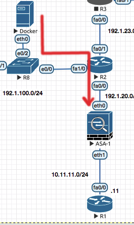
! ASA 1

! 1. Enable WebVPN on the outside interface and disable anyconnect-essentials

webvpn
 enable outside
 no anyconnect-essentials

! 2. Configure a Group Policy to specific the anyconnect client

group-policy SALES internal
group-policy SALES attributes
 banner value "Ony Auth Personnel"
 vpn-tunnel-protocol ssl-clientless

! 3. Configur ea user and make it part of the group policy

username cisco6 password cisco123
username cisco6 attributes
 vpn-group-policy SALES

! 4. Configure the Port-forwarding for Non-Native applications

webvpn
 port-forward SALES 29001 10.11.11.4 1421
 port-forward SALES 29002 10.11.11.11 23
!
group-policy SALES attribute
 webvpn
  port-forward value SALES
!
You can then browse to the external page
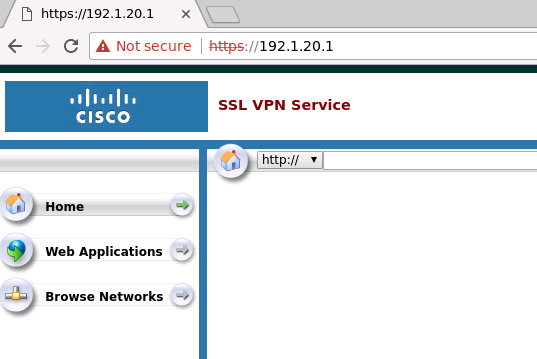
Firepower and FTD
Firepower is the IPS Only , FTD is Firewall Code + IPS .
You can add SSD to the ASA and install the FTD OS on it .
To configure IP Address on FMC
sudo su
configure-network ! Shell script
! Point the FTD towards FMC
configure manager add 192.168.1.66 cisco123
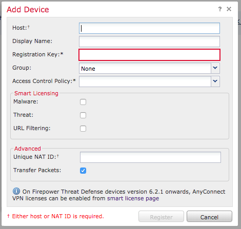
Access Control Policy : Is the default Firewall behaviour , Block All traffic , Allow all traffic etc .
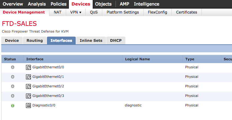
After you make changes on FMC , the changes arent depolyed untill you manually push it from the FMC (Using the Deploy Button) .
Notice the “Show Rule Conflict” ; It tells you if a rule conflicts with other and help you do the ordering of the rules.

Things to Do :
- CREATE Access Control Policy
- Add Rule : INT TO OUT : Allow from Inside Zone to Outside Zone
- Add Rule : In to Out : Block FB , Using the Applications Tab .
- Drag Rule 2 above Rule 1
- Enable R1 to telnet and ping into R3 . (Outside to DMZ) . For PING you may need to create the port manually .
- Configure Static Routing on the FTD .
- Create a Loopback network on a connected Router
- Point to the Loopback Network from the FTD , via the Interface on the FTD , poining to the nexthop.
- Also create a static router , like Source 2.2.2.2 going to Router Next hop or 3.3.3.3
- Create an OSPF Neighborship with an external Router .
- Keep it simple on How would you run the OSPF on the router.
- Create a RIP Routing like step 7 and do a re-distribution between the OSPF and RIP
- Create NAT Scenario to do Object NAT . Both Static and Dynamic .
-
Do a Port Translation as Well , say SimpleHTTPServer 80 : 8080
-
Try doing Twice NAT
- Do a Face Block by ACL for internal users .
- Create an Intrusion POlicy and try sending an threat . FOR604 virus .
- Stop people to be able to upload a document or PPT File .
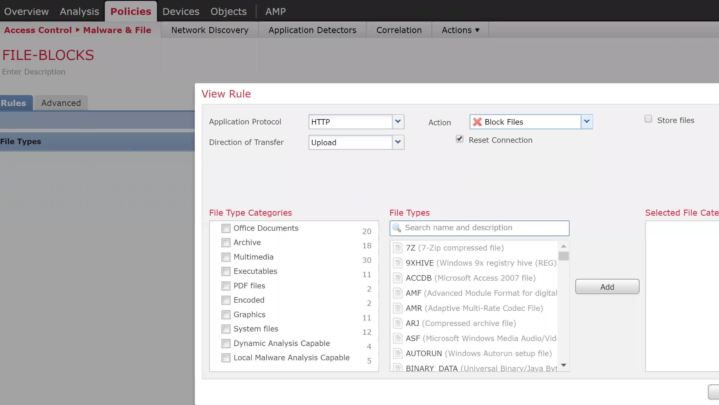
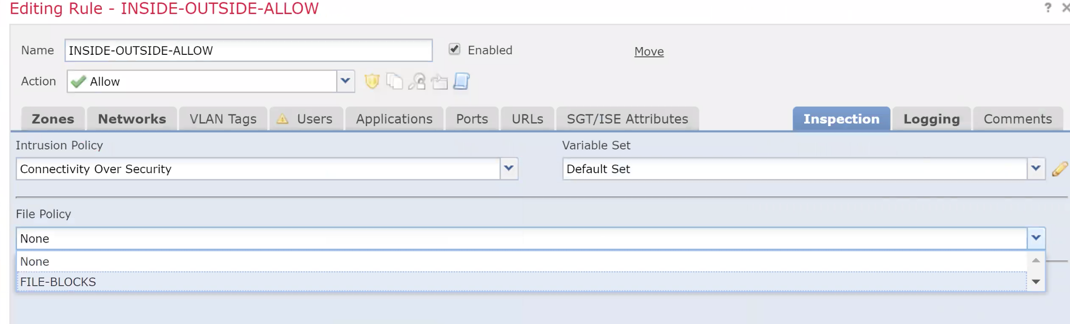
- Configure a Site to Site VPN between to FTD connected to the same FMC
- Create the VPN
- Create the access list on eact ftd to define the interesting traffic
Anti-Spoofing ACLs
To stop spoofed IP Address , you can use ACLs on an interface and define what IP you would like to block which are sourced from your network (but does not logically come from that interface)
uRPF Reverse Path Forwarding Check
Using uRPF instead of creating an ACL for every network you can use this technology to do it automatically for you .
It checks the source of a packet agains the routing table and if the return path of the packet is same as the source , it is allowed .
uRPF Configuration
ip verify unicast source reachable-via rx allow-default
! allow-default means check the default gateway of the source packet , and if: its pointing in the right direction let it go.
There could be case where the packet is coming in from one interface but is exiting out from another interface (typical in case of multiple ISP links to a router) . In this case uRPF migh block this genuine flow and an exception would have to be made . The same can be defined by the use of ACLs (ACL 150 in this example).
ip verify unicast source reachable-via rx allow-default 150
To log RPF packets , create a log ACL and add it to the RPF command (like the example above)
The above is an example of strict RPF check denoted by rx .
If you change the rx to any it means that as long as the reverse path is in the routing table its allowed. (Not confinign it to the interface it came in from)
ip verify unicast source reachable-via any
Switchport port security
Switch port security commands
The command below manually assigns an MAC Address
switchport port-security mac XXXX.XXXX.XXXX
The command below assigns an sticky MAC Address , which means the first MAC is allowed and others are not.
switchport port-security mac sticky
The command below will limit the maximum amount of MAC addresses which can be learned on an interface.
switchport port-security max 5
Once a switch is put in the error disable mode , you can set the recovery time like the following :
errdisable recovery cause psecure-violation
errdisable recovery interval 180 ! Time after which recovery can happen.
DHCP Snooping
DHCP Snopping is to make sure that only a valid DHCP Server is used to respond to the DHCP request and any rogue DHCP Server cannot offer the DHCP OFFER.
ip dhcp snooping ! Turn the feature on
ip dhcp snooping vlan 10 ! Enable for the appropriate VLAN.
The above command will basically stop DHCP on the entire VLAN 10 untill you enable / trust the port to which the DHCP server is connected.
int gi0/3 ! Port to which the DHCP Server is connected.
 ip dhcp snooping trust
In case of switch connected to the other switch on which the DHCP Server is connected , the trunk port would be configured as the trusted port.
As a result of DHCP Configuration , the switch maintains a DHCP Snooping table of assigned IP Addresses and ports.
ARP Inspection
ARP Inspection is to save from ARP Poisining (MITM) type attacks.
ARP inspection basically uses the DB built by DHCP snooping to match the right MAC adresses on the switch port .
ip dhcp snooping ! Turn the feature on
ip dhcp snooping vlan 10 ! Enable for the appropriate VLAN.
ip arp inspection vlan 10
int gi0/3 ! Port to which the DHCP Server is connected.
 ip dhcp snooping trust
 ip arp inspection trust
Source Gaurd
Source gaurd combines the capabilities of port security and arp inspection.
int gi0/3 ! Port to which the Sourcegaud is to be enabled.
 ip verify source
This will ensure the port is checked for MAC , IP , VLAN and Port against the DHCP Snooping DB.
VLAN ACL
Allows you to control traffic withing the VLAN , going in and out of a VLAN.
1. Classify the traffic

access-list 100 permit icmp any any
access-list 100 permit udp eq .... whatever


2. Create the ACL

vlan access-map VMAP 10
 match ip address 100
 action drop
vlan access-map VMAP 20
 action forward

3. Apply the VLAN ACL to the appropriate VLAN

vlan filter VMAP vlan-list 10,20
WSA (Web Security Agent)
Web Filtering and Caching (Adult,Gambling,News,Sports,Social Networks etc) WSA has Proxy ports apart from managment labbeled as P1 / P2 .
There are two modes
- Inline mode
- Transparent Mode
In inline mode the browsers/end computes know about the WSA , in transparent mode the end devices are pointing to the default gateway which in turn talks to the WSA via WCCP .
GUACAMOLE Ctrl+C Ctrl+V [CTRL+ALT+SHIFT]
Username : admin Password : ironport
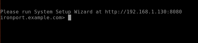
Please run System Setup Wizard at http://192.168.1.130:8080 ironport.example.com>
Please run System Setup Wizard at http://192.168.1.130:8080
ironport.example.com> se
setntlmsecuritymode, setgateway, sethostname, settime, settz
ironport.example.com> in
interfaceconfig, intrelay
If you are stuck at the login page with nothing happening when you hit the login button you my be hitting a defect . Try installing the Tampermonekey script https://www.cisco.com/c/en/us/support/docs/security/email-security-appliance/211583-Cisco-ESA-WSA-SMA-Login-Workaround.html
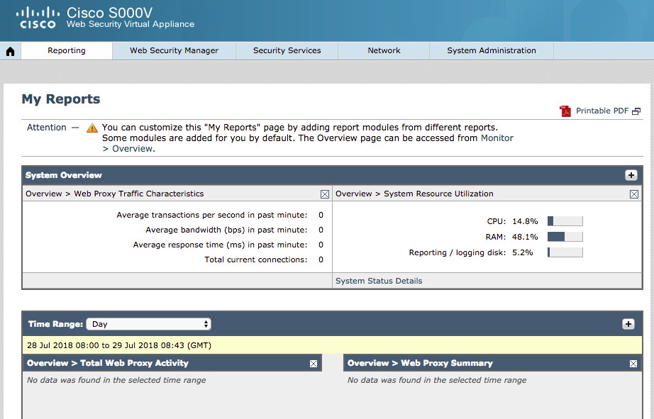
WSA Licensing
Enable FTP on the system and commit the changes . Copy the license file in the configuration folder.
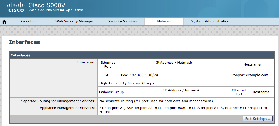
https://slexui.cloudapps.cisco.com/SWIFT/LicensingUI/Quickstart#
To enable WCCP on WSA
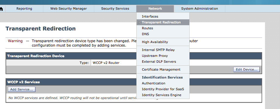
Configuring WCCP on ASA
1. Configure the IP Address of the WSA in an ACL

access-list WSA_ACL permit ip host 192.168.1.10 any ! IP Address of the WSA

2. Configure the ACL that specifies what traffic needs to be redirected

access-list 101 permit tcp any any eq 80
access-list 101 permit tcp any any eq 8080

3. Setup a Tunnel between the redirectign device (in this Scenario a Switch) and the WCCP Server.

> The tag needs to match on the Switch and the WCCP Server

wccp 99 group-list WSA_ACL redirect-list REDIRECT ! It means that and traffic matching the REDIRECT ACL should be sent to the WSA (WSA_ACL)
with a service tag of 99

4. Apply the WCCP Redirection to the interface (of the device doing redirection)

wccp 99 redirect in interface inside
Configuring WCCP on Router
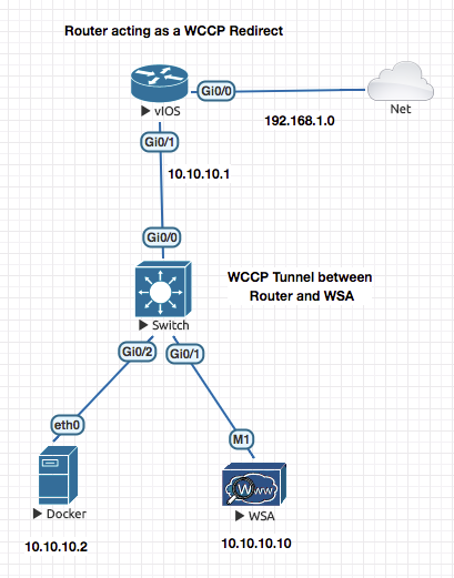
On a switch you need to configure
sdm prefer routingand reload.
Enable WCCP

ip wccp ver 2

1. Configure the IP Address of the WSA in an ACL

access-list 101 permit ip host 10.10.10.10 any! IP Address of the WSA

2. Configure the ACL that specifies what traffic needs to be redirected

access-list 102 permit tcp any any eq 80
access-list 102 permit tcp any any eq 8080

3. Setup a Tunnel between the redirectign device  and the WCCP Server.

> The tag needs to match on the Switch and the WCCP Server

ip wccp 99 group-list 101 redirect-list 102 ! It means that and traffic matching the REDIRECT ACL should be sent to the WSA (WSA_ACL)
with a service tag of 99

4. Apply the WCCP Redirection to the interface (of the device doing redirection)

interface f0/1
 ip wccp 99 redirect in
show ip wccp 99 view
Configuring the WSA Side
- Change the Mode to WCCP
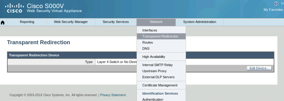
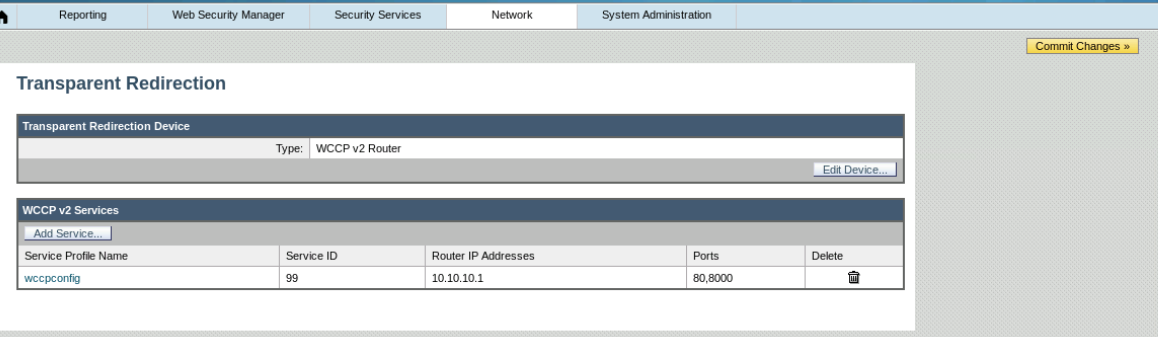
Dont forget to commit chnages .
After commiting the changes you will see the following happen on the router
Router#sh ip wccp 99 view
*Aug  5 05:32:45.617: %WCCP-5-SERVICEFOUND: Service 99 acquired on WCCP client 10.10.10.10
    WCCP Routers Informed of:
	192.168.1.106

    WCCP Clients Visible:
	10.10.10.10
At this stage a session between the router and the WSA is established
- Now go to the Web proxy Settings and add any no 80 ports to the proxy settings.
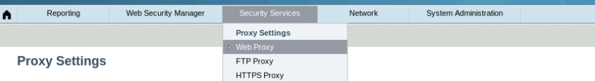
Now you will set your policies
Now to set and define your internet access policies you have to first define the end users in groups . This can be based on their IP Address or Group information received from AD (WSA intergrates with AD)
Go to Identification Profiles
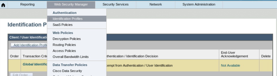
Define / Create the EXEC and SALES policies
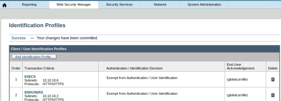
Now create the Access Policy
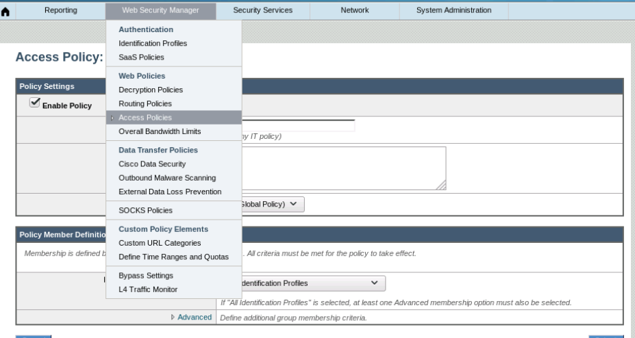
This is where you block the categories and applications
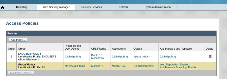
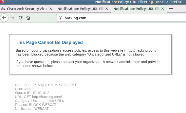
ESA (Email Security Agent)
SMTP is for sendign emails. This is mainly where WSA is used.
POP or IMAP is used to download/receive the mails by the clients.
Start @00:44:00
- Cretae the DNS Entries on DNS Server
- Check Resolution of IMAP and SMTP Hostnames . Smatp.servername.com
- Configure the Hmail Server and Add Accounts
- Test email sendign between the same servers
- Test Email Server between the domains (No WSA YET)
Cisco ASA with Anyconnect VPN using SSL or IKEv1/v2
Clientless VPNs are limited and convoluted to access WEB , FTP and CIFS.
Cisco ISE
Device Profiling
Profilinig is performed by policy services node.
In a typical open network any device can get an IP address and more often then not it is all access.
From a network admin perspective you would like to know whats connected to your network and also limit access based on device type.
There are various probes which can help which can help gather as much details as possible.
Profiling enables ISE to recognise the device and understand what it is. It enables ISE to know the type of client endpoint.
Profiling is made up to two components :
Probes: Probes Allows ISE to collect different device attributes. Profiling Policies : ISE Allows to match these device attribute to further define which policies does it map to .
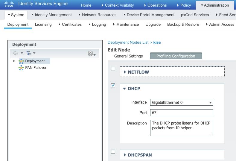
DHCP : Setup via Helper Address / DHCP Relay
HTTP : Browser type , OS Type in the User Agent Attribute (When URL Redirect Happens)
RADIUS : Attributed coming in via Dot1.X
DNS : ISE to be able to reverse lookup and get hostname.
AAA Switch configuration
aaa authentication login default local
aaa authentication login NOAUTH none
aaa authentication  dot1x default group radius
aaa authorization network default group radius
aaa accounting update newinfo periodic 3
aaa accounting indentity default start-stop group radius
aaa acciunting system default start-stop group radius

device-sensor notify all-changes ! Allows switch to gather info and send it to ise.

logging host X.X.X.X transport udp port 20514 ! Allows Switch log messages to be sent to ISE
ip helper-address X.X.X.X on the VLAN of the devices pointing to the ISE Server.
Wireless
- APs job is to only talk to the WLC , so it can be an Access Port
- AP Gets the IPAddress ont he Access port and also the option 43 pointing to WLC.
- It then tries to register to the WLC.
debug mac addr 1c:6a:7a:5a:73:90 debug client 1c:6a:7a:5a:73:90 debug capwap events enable debug capwap errors enable debug pm pki enable
*Oct 28 03:51:52.000: %CAPWAP-5-DTLSREQSEND: DTLS connection request sent peer_ip: 10.10.10.3 peer_port: 5246 *Oct 28 03:51:52.247: %CAPWAP-5-DTLSREQSUCC: DTLS connection created sucessfully peer_ip: 10.10.10.3 peer_port: 5246 *Oct 28 03:51:52.247: %CAPWAP-5-SENDJOIN: sending Join Request to 10.10.10.3perform archive download capwap:/ap3g2 tar file *Oct 28 03:51:52.699: %CAPWAP-6-AP_IMG_DWNLD: Required image not found on AP. Downloading image from Controller. *Oct 28 03:51:52.703: Loading file /ap3g2…
(Cisco Controller) >show ap bundle all
Primary AP ImageSizeSupported AP’s
ap1g113560AP700 ap1g315392AP1530 ap1g430268AP1850/1810 ap1g530476AP1815,1540 ap1g626552AP2900 ap3g347444AP2800,3800,4800,1560 c157013060AP1570 c370014380AP1700,2700,3700
Secondary AP ImageSizeSupported AP’s
ap1g113560AP700 ap1g315392AP1530 ap1g430268AP1850/1810 ap1g530476AP1815,1540 ap1g626552AP2900 ap3g347444AP2800,3800,4800,1560 c157013060AP1570
–More– or (q)uit c370014380AP1700,2700,3700
**Reset the AP **
- Remove Power
- Press and hold mode button and insert power
- you must continue to hold the MODE button until the light indicator on top of AP is solid red!
- Leave the MODE button .
- YOu should be the “ap:” mode 6. ap: dir flash: ap: delete flash:private-multiple-fs ap: reset
Username: Cisco Password: ! here we type Cisco
Username: Cisco Password: ! here we type Cisco
AP78da.6ee0.2655> AP78da.6ee0.2655>en Password: ! this is also Cisco AP78da.6ee0.2655#
Now we can reinstall our vWLC and connect our APs back to it. On our APs we may also do:
AP78da.6ee0.2655# AP78da.6ee0.2655#clear capwap private-config AP78da.6ee0.2655# AP78da.6ee0.2655#reload Proceed with reload? [confirm]
AP1c6a.7a5a.7390> AP1c6a.7a5a.7390> Translating “CISCO-CAPWAP-CONTROLLER”…domain server (192.168.1.1)
*Mar 1 00:01:03.063: %CAPWAP-3-ERRORLOG: Did not get log server settings from DHCP. *Mar 1 00:01:03.067: %CAPWAP-3-ERRORLOG: Could Not resolve CISCO-CAPWAP-CONTROLLER AP1c6a.7a5a.7390> *Mar 1 00:01:13.067: %CAPWAP-3-ERRORLOG: Go join a capwap controller *Oct 28 04:10:16.000: %CAPWAP-5-DTLSREQSEND: DTLS connection request sent peer_ip: 10.10.10.3 peer_port: 5246 examining image… *Oct 28 04:10:18.303: %CAPWAP-5-DTLSREQSUCC: DTLS connection created sucessfully peer_ip: 10.10.10.3 peer_port: 5246 *Oct 28 04:10:18.303: %CAPWAP-5-SENDJOIN: sending Join Request to 10.10.10.3perform archive download capwap:/ap3g2 tar file *Oct 28 04:10:18.431: %CAPWAP-6-AP_IMG_DWNLD: Required image not found on AP. Downloading image from Controller. *Oct 28 04:10:18.435: Loading file /ap3g2… set_radio_pwr_mode: bad radio unit# 0 set_radio_pwr_mode: bad radio unit# 1
*Oct 28 04:10:49.287: %CDP_PD-4-POWER_OK: Full power - NEGOTIATED inline power source ., 1)28 04:11:06.435: %CAPWAP-3-ERRORLOG: Retransmission count for packet exceeded max(CAPWAP_ECHO_REQUEST %Error opening flash:/update/info (No such file or directory) ERROR: Image is not a valid IOS image archive. Download image failed, notify controller!!! From:7.6.1.118 to 0.0.0.0, FailureCode:3
archive download: takes 53 seconds
*Oct 28 04:11:11.435: %SYS-3-MGDTIMER: Uninitialized timer, timer stop, timer = 3AFC900. -Process= “CAPWAP CLIENT”, ipl= 0, pid= 73 -Traceback= 119AF80z 12A89C8z 12AA11Cz 16F32C8z 1762360z 16FD224z 1725FFCz 17278A4z 171E070z 1728184z 171E374z 17305D8z 173C56Cz 1728250z 176052Cz 172E614z *Oct 28 04:11:11.435: %LWAPP-3-CLIENTERRORLOG: LWAPP LED Init: incorrect led state 255 *Oct 28 04:11:11.435: %LWAPP-3-CLIENTERRORLOG: Config load from flash failed. Initialising Cfg
Unable to create temp dir “flash:/update” Download image failed, notify controller!!! From:7.6.1.118 to 0.0.0.0, FailureCode:7
Look at the AP Consoloe Logs
**Finnaly Loading the Right Code on The AP Resolved the issue”
archive download-sw /force-reload /overwrite tftp://10.10.10.1/c1140-rcvk9w8-tar.124-25d.JA.tar
k9w8- Lightwiehgt Mode k9w7 - Autonmous mode
Helpfull lInks
https://www.speaknetworks.com/converting-cisco-wireless-access-point-lightweight-mode-autonomous-mode-vice-versa/ https://blog.it-playground.eu/lightweight-ap-manual-firmware-upgrade/ https://community.cisco.com/t5/wireless-and-mobility/downgrading-software-on-lightweight-access-point/td-p/3025985 https://mrncciew.com/2012/10/20/lightweight-to-autonomous-conversion/
If your configured SSIDs are not showing up , make sure tha your AP mode is set to FlexConnect
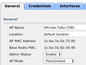
All SSID Getting IP from Managment VLANs
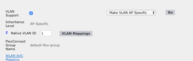
Next Step to make WLC Managment IP in a specific VLAN and rest in other VLANs.
–
Difference Between Flexconnect and Local
In local mode, an AP creates two CAPWAP tunnels to the WLC. One is for management, the other is data traffic. This behavior is known as “centrally switched” because the data traffic is switched(bridged) from the ap to the controller where it is then routed by some routing device.
Flex Connect also known as HREAP by the old timers, allows data traffic to be switched locally and not go back to the controller. It basically causes the AP to behave like an autonomous AP, but be managed by the WLC. In this mode, the AP can still function even if it looses connection with the controller.
Centrally Switched VLANs
Make sure the VLANs are centrally switched when using a virtual WLC
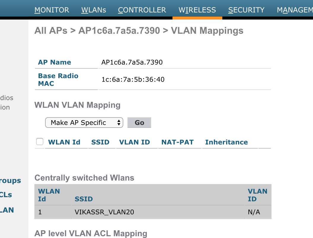
Make sure central switching is disabled
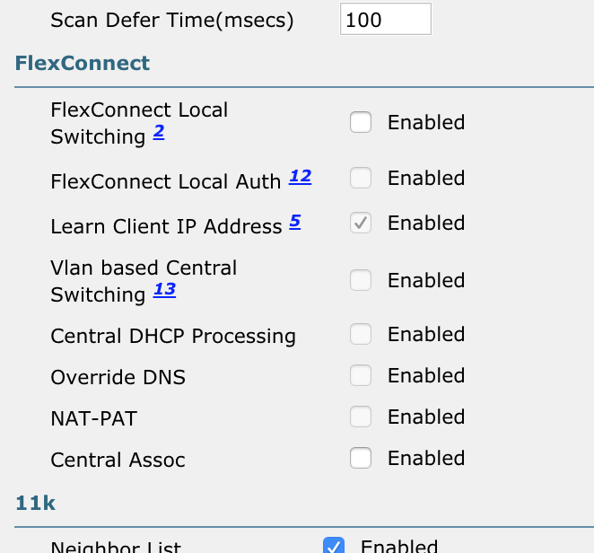
ip dhcp pool VIRTUAL_NET_30_DHCP_POOL network 10.10.30.0 255.255.255.0 default-router 10.10.30.1 dns-server 192.168.1.1 option 43 ip 10.10.10.3 ip address dhcp
–
Technotes
*FMC Setup **
sudo /usr/local/sf/bin/configure-network
vWLC Troubleshooting
(Cisco Controller) >show network summary
By Default you should access the WLC via the HTTPs interface. HTTP is disabled by default.
ASDM Configuration
After configuring an interface as nameif managment , give it IP and follow the steps below
For
asdm-782-151.binuse 32 bit ,Java to 7 update 45. Always refer the ASDM version guide on cisco.com to check for Java Dependencies than google :)
JNLP URL for ASDM is
https://X.X.X.X/admin/public/asdm.jnlp
enable pass cisco
username cisco password cisco
aaa authentication ssh console LOCAL
crypto key generate rsa modulus 1024

asdm image flash:/asdm-782-151.bin .bin
http server enable
!  Enable Source Traffic
http 192.168.1.0 255.255.255.0 management
!  Enable Source Traffic
ssh 192.168.1.0 255.255.255.0 management
General Router Default Config
conf t
logging synchronous
line con 0
 exec-time 0
Troubleshooting Commands and Outputs
R1#show crypto ikev2 sa
R1#clear crypto ikev2 sa X.X.X.X
R1#show crypto isakmp sa
IPv4 Crypto ISAKMP SA
dst             src             state          conn-id slot status
192.1.20.2      192.1.10.2      QM_IDLE           1001    0 ACTIVE
R1#show crypto ipsec sa

interface: FastEthernet0/0
    Crypto map tag: CMAP, local addr 192.1.10.2

   protected vrf: (none)
   local  ident (addr/mask/prot/port): (10.1.1.0/255.255.255.0/0/0)
   remote ident (addr/mask/prot/port): (10.2.2.0/255.255.255.0/0/0)
   current_peer 192.1.20.2 port 500
     PERMIT, flags={origin_is_acl,}
    #pkts encaps: 5, #pkts encrypt: 5, #pkts digest: 5
    #pkts decaps: 5, #pkts decrypt: 5, #pkts verify: 5
    #pkts compressed: 0, #pkts decompressed: 0
    #pkts not compressed: 0, #pkts compr. failed: 0
    #pkts not decompressed: 0, #pkts decompress failed: 0
    #send errors 5, #recv errors 0

     local crypto endpt.: 192.1.10.2, remote crypto endpt.: 192.1.20.2
     path mtu 1500, ip mtu 1500, ip mtu idb FastEthernet0/0
     current outbound spi: 0x99D47D47(2580839751)

     inbound esp sas:
      spi: 0x890A3034(2299146292)
        transform: esp-3des esp-md5-hmac ,
        in use settings ={Tunnel, }
        conn id: 1, flow_id: SW:1, crypto map: CMAP
        sa timing: remaining key lifetime (k/sec): (4415180/3433)
        IV size: 8 bytes
        replay detection support: Y
        Status: ACTIVE

     inbound ah sas:

     inbound pcp sas:

     outbound esp sas:
      spi: 0x99D47D47(2580839751)
        transform: esp-3des esp-md5-hmac ,
        in use settings ={Tunnel, }
        conn id: 2, flow_id: SW:2, crypto map: CMAP
        sa timing: remaining key lifetime (k/sec): (4415180/3433)
        IV size: 8 bytes
        replay detection support: Y
        Status: ACTIVE

     outbound ah sas:

     outbound pcp sas:
Clearing the crypto session
R3#clear cryp
R3#clear crypto sa
R3#
*Mar  1 05:13:32.002: %GDOI-4-GM_RE_REGISTER: The IPSec SA created for group ABC may have expired/been cleared, or didn not go through. Re-register to KS.
Error Messages and Resolution
*Mar 1 00:42:09.431: %CRYPTO-4-IKMP_BAD_MESSAGE: IKE message from 192.1.20.2 failed its sanity check or is malformed
The above warrants a key mismatch .
*Mar  1 01:34:18.575: %DUAL-5-NBRCHANGE: IP-EIGRP(0) 100: Neighbor 192.168.1.3 (Tunnel0) is down: retry limit exceeded
*Mar  1 01:34:21.279: %DUAL-5-NBRCHANGE: IP-EIGRP(0) 100: Neighbor 192.168.1.3 (Tunnel0) is up: new adjacency
*Mar  1 01:34:22.259: %DUAL-5-NBRCHANGE: IP-EIGRP(0) 100: Neighbor 192.168.1.2 (Tunnel0) is down: retry limit exceeded
This was caused due to the following commands missing from the DMVPN Clients
ip nhrp map multicast 192.1.10.2
packet-tracer input INSIDE tcp [SRC_HOST] [SRC_PORT] [DST_HOST] [DST_PORT]

asa-fw# packet-tracer input INSIDE tcp 172.16.1.5 1024 4.2.2.2 9000

!!! output truncated

Phase: 4
Type: ACCESS-LIST
Subtype: log
Result: DROP                                            <---- ASA Dropped the traffic
Config:
access-group INSIDE_in in interface INSIDE
access-list INSIDE_in extended deny ip any4 any4 log    <---- This rule denied the traffic
Additional Information:

Result:
input-interface: INSIDE
input-status: up
input-line-status: up
output-interface: OUTSIDE
output-status: up
output-line-status: up
Action: drop
Drop-reason: (acl-drop) Flow is denied by configured rule   <----
asa-fw# capture DENY type asp-drop all buffer 500000 match tcp host 172.16.1.5 host 4.2.2.2 eq 9000


asa-fw# sh capture DENY trace

1 packet captured
1: 06:13:43.434761       802.1Q vlan#200 P0 172.16.1.5.33489 > 4.2.2.2.9000: S
   884023774:884023774(0) win 14600 <mss 1460,sackOK,timestamp 67442169 0,nop,wscale 7>
   Drop-reason: (acl-drop) Flow is denied by configured rule
                           ^^^^^^^^^^^^^^^^^^^^^^^^^^^^^^^^^

1 packet shown
asa-fw# no capture DENY
Eve-NG Docker IP Address Configuration (in the Starup config of the docker )
ip addr add 192.168.1.20/24 dev eth0
ip route add default via 192.168.1.1
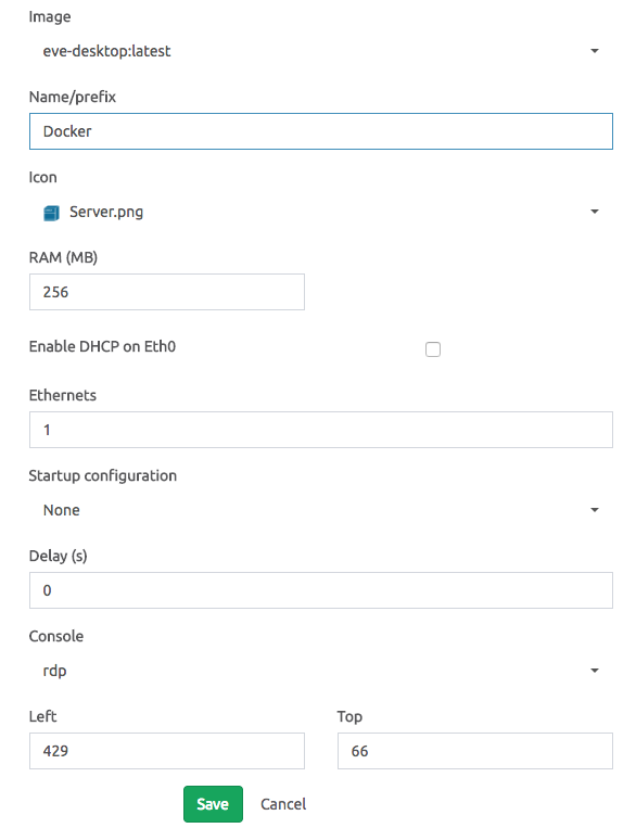
Subscribe via RSS