Cisco NSO Learnings
by Vikas Srivastava
Opinions expressed are solely my own and do not express the views or opinions of my employer.
NCS Installation
This lab exercise was conducted with
nso-4.6.linux.x86_64.installer.binIt is advisable to use the same while following this document.
Make sure Java 10 (not Open JDK) Installed java -version and ant are installed.
Install NCS
```shell linenums=”2” hl_lines=”1 4-5” root@mininet-vm:/home/mininet# chmod +x nso-4.6.linux.x86_64.installer.bin root@mininet-vm:/home/mininet# ./nso-4.6.linux.x86_64.installer.bin /opt/ncs
#### Setup NCS

```shell
root@mininet-vm:/home/mininet# source /opt/ncs/ncsrc
root@mininet-vm:/home/mininet# ncs-setup --dest $NCS_DIR/ncs-run
root@mininet-vm:/home/mininet# cd $NCS_DIR/ncs-run
# Start the NCS Server
root@mininet-vm:~/ncs-run# ncs
Check NCS Status
ncs --status | grep status
ncs --version
3.4.2
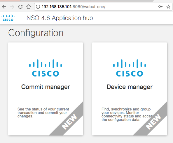
NCS/NSO via the WebUI
Type http://127.0.0.1:8080/login.html
Connect to the NCS CLI
ncs_cli -u admin -C
What are the packages availaible
root@mininet-vm:~# cd $NCS_DIR
root@mininet-vm:/opt/ncs# ls packages/neds/
a10-acos  cisco-ios  cisco-iosxr  cisco-nx  dell-ftos  juniper-junos
Compile a new NED
Unfortunately, the majority of existing devices in current networks do not speak NETCONF and SNMP is usually mostly used to retrieve data from devices. By far the most common way to configure network devices is through the CLI. Management systems typically connect over SSH to the CLI of the device and issue series of CLI configuration commands. Some devices do not even have a CLI, and thus SNMP, or even worse, various proprietary protocols, are used to configure the device. NSO can speak southbound not only to NETCONF-enabled devices, but through the NED architecture it can speak to an arbitrary management interface.
nso-ned-4.6.pdf
Compile the Cisco IOS NED package by issuing the make command. Make sure that the compilation of the NED and netsim (the part used to emulate Cisco IOS CLI which will be used throughout this course) is successful.
root@mininet-vm:/opt/ncs/packages/neds/cisco-ios/src# make
cd java && ant -q all

BUILD SUCCESSFUL
Total time: 0 seconds
cd ../netsim && make all
make[1]: Entering directory /opt/ncs/packages/neds/cisco-ios/netsim
make[1]: Nothing to be done for all.
make[1]: Leaving directory /opt/ncs/packages/neds/cisco-ios/netsim
Do the same for IOS-XR
root@mininet-vm:/opt/ncs/packages/neds/cisco-iosxr# cd src
root@mininet-vm:/opt/ncs/packages/neds/cisco-iosxr/src# make
cd java && ant -q all

BUILD SUCCESSFUL
Total time: 0 seconds
cd ../netsim && make all
make[1]: Entering directory /opt/ncs/packages/neds/cisco-iosxr/netsim
make[1]: Nothing to be done for all.
make[1]: Leaving directory /opt/ncs/packages/neds/cisco-iosxr/netsim
The two NEDs are now compiled and available for use but they are not available to the running instance of NSO. One of the ways to make them available to the running instance is by linking a directory in the ncs-run/packages directory to point to the location of the NEDs in the packages subdirectory in the installation directory (i.e. $NCS_DIR)
To link the newly compiled NEDS
cd $HOME/ncs-run/packages
ln -s /opt/ncs/packages/neds/cisco-ios cisco-ios
ln -s /opt/ncs/packages/neds/cisco-iosxr cisco-iosxr
Login and reload the packages
ncs_cli -C -u admin
root@ncs# packages reload

>>> System upgrade is starting.
>>> Sessions in configure mode must exit to operational mode.
>>> No configuration changes can be performed untill upgrade has completed.
>>> System upgrade has completed successfully.
reload-result {
    package cisco-ios
    result true
}
reload-result {
    package cisco-iosxr
    result true
}
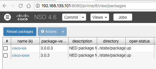
You can also verify this with show packages as well
Next Objective is to Add emulated devices to the NSO and perform some intial taks like Synchornize Config , Create Device Groups , and make sure all devices share the same config.
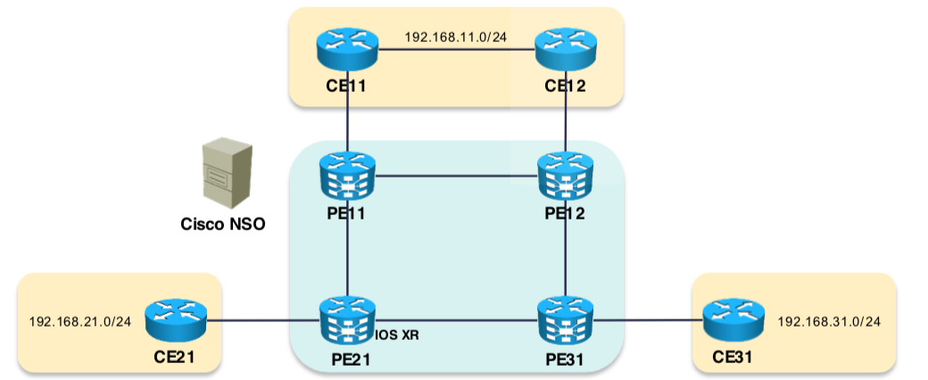
Add Emulated Devices to the Network
Now we will neither use real or virtual devices but use emulated deives
Create device with Net Sim
ncs-netsim create-device cisco-ios PE11
ncs-netsim add-device cisco-ios PE12
ncs-netsim add-device cisco-iosxr PE21
ncs-netsim add-device cisco-ios PE31
ncs-netsim add-device cisco-ios CE11
ncs-netsim add-device cisco-ios CE12
ncs-netsim add-device cisco-ios CE21
ncs-netsim add-device cisco-ios CE31

# Bulk Export for easy import
ncs-netsim ncs-xml-init > devices.xml

# And then Bulk Import to NCS
ncs_load -l -m devices.xml

admin@ncs# show devices brief
NAME  ADDRESS    DESCRIPTION  NED ID
------------------------------------------
CE11  127.0.0.1  -            cisco-ios
CE12  127.0.0.1  -            cisco-ios
CE21  127.0.0.1  -            cisco-ios
CE31  127.0.0.1  -            cisco-ios
PE11  127.0.0.1  -            cisco-ios
PE12  127.0.0.1  -            cisco-ios
PE21  127.0.0.1  -            cisco-ios-xr
PE31  127.0.0.1  -            cisco-ios
R1    127.0.0.1  -            cisco-ios
You can actually connect to a Virtual Emulated router by the
ncs-netsim
root@cisco-virtual-machine:/opt/ncs/ncs-run/packages/l2vpn/templates# ssh admin@127.0.0.1 -p 10022
admin@127.0.0.1's password:admin

admin connected from 127.0.0.1 using ssh on cisco-virtual-machine
PE11> en
PE11#
Or you can connect to virtual device like this:
$ ncs-netsim cli-i c1
c1> enable
c1# show running-config
Now connect to the your NCS CLI ncs_cli -C -u admin and add the device to the NCS
config
 devices device R1
  address 127.0.0.1 port 10022
  device-type cli ned-id cisco-ios protocol ssh
  authgroup default
  state admin-state unlocked
commit
Now connnec to the device and fetch the configuration from them
devices fetch-host-keys
devices sync-from
end
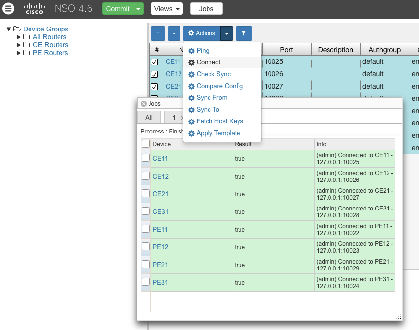
Create Device Group
Now lets add the devices added above to a device group
admin@ncs(config)# devices device-group "PE Routers"
admin@ncs(config-device-group-PE Routers)# device-name [ PE11 PE12  PE21  PE31 ]
admin@ncs(config-device-group-PE Routers)# top
admin@ncs(config)# devices device-group "CE Routers"
admin@ncs(config-device-group-CE Routers)# device-name [ CE11 CE12 CE21 CE31 ]
admin@ncs(config-device-group-CE Routers)# top
admin@ncs(config)# devices device-group "All Routers"
admin@ncs(config-device-group-All Routers)# device-group [ "PE Routers" "CE Routers" ]
admin@ncs(config-device-group-All Routers)# top
Now lets verify the configuration and commit it .
admin@ncs(config)# show configuration
devices device-group "All Routers"
!
devices device-group "PE Routers"
 device-name [ PE11 PE12 PE21 PE31 ]
!
devices device-group "CE Routers"
 device-name [ CE11 CE12 CE21 CE31 ]
!
devices device-group "All Routers"
 device-group [ "CE Routers" "PE Routers" ]
!
admin@ncs(config)# commit
Commit complete.
admin@ncs(config)#
You can verify the above by
admin@ncs# show devices device-group member
NAME         MEMBER
----------------------------------------------------------
All Routers  [ CE11 CE12 CE21 CE31 PE11 PE12 PE21 PE31 ]
CE Routers   [ CE11 CE12 CE21 CE31 ]
PE Routers   [ PE11 PE12 PE21 PE31 ]
Interesting Screen Shot
Create Customer
Now lets create a customer
admin@ncs(config)# customers customer ACME
admin@ncs(config-customer-ACME)# rank 1
admin@ncs(config-customer-ACME)# status active
admin@ncs(config-customer-ACME)# top
admin@ncs(config)# commit
Commit complete.
admin@ncs(config)#


admin@ncs# show running-config customers
customers customer ACME
 rank   1
 status active
!
Lets now create a Device template
admin@ncs# config
admin@ncs(config)# devices template "Common Device Parameters" config
admin@ncs(config-config)# ios:?
admin@ncs(config-config)# ios:ip domain name cisco.com
admin@ncs(config-config)# ios:ip name-server [ 192.168.133.1 ]
admin@ncs(config-config)# ios:ntp server server-list 10.0.0.1
admin@ncs(config-server-list-10.0.0.1)# exit
admin@ncs(config-config)# cisco-ios-xr:domain name cisco.com
admin@ncs(config-config)# cisco-ios-xr:domain name-server 192.168.133.1
admin@ncs(config-name-server-192.168.133.1)# exit
admin@ncs(config-config)# cisco-ios-xr:ntp server 10.0.0.1
admin@ncs(config-server-10.0.0.1)# exit
admin@ncs(config-config)# commit
Commit complete.
Verify the configuration above
admin@ncs(config)# show full-configuration devices template Common\ Device\ Parameters
devices template "Common Device Parameters"
 config
  cisco-ios-xr:domain name cisco.com
  cisco-ios-xr:domain name-server 192.168.133.1
  !
  cisco-ios-xr:ntp server 10.0.0.1
  !
  ios:ip domain name cisco.com
  ios:ip name-server [ 192.168.133.1 ]
  ios:ntp server server-list 10.0.0.1
  !
 !
!
admin@ncs(config)#
Now apply the configuration above to all the routers
admin@ncs(config)# devices device-group All\ Routers apply-template template-name Common\ Device\ Parameters
apply-template-result {
    device CE11
    result ok
}
apply-template-result {
    device CE12
    result ok
}
apply-template-result {
    device CE21
    result ok
}
apply-template-result {
    device CE31
    result ok
}
apply-template-result {
    device PE11
    result ok
}
apply-template-result {
    device PE12
    result ok
}
apply-template-result {
    device PE21
    result ok
}
apply-template-result {
    device PE31
    result ok
}
Note that from the above command the configuration is still not applied on the routers unless it is commited .
Lets do a dry run before comiting it
admin@ncs(config)# commit dry-run
cli {
    local-node {
        data  devices {
                  device CE11 {
                      config {
                          ios:ip {
                              domain {
             +                    name cisco.com;
                              }
             +                name-server 192.168.133.1;
                          }
                          ios:ntp {
                              server {
             +                    server-list 10.0.0.1 {
             +                    }
                              }
                          }
                      }
                  }
                  device CE12 {
                      config {
                          ios:ip {
                              domain {
             +                    name cisco.com;
                              }
             +                name-server 192.168.133.1;
                          }
                          ios:ntp {
                              server {
             +                    server-list 10.0.0.1 {
             +                    }
                              }
                          }
                      }
                  }

admin@ncs(config)# commit
Commit complete.
Now that we have the configuration applied, lets check on the devices individually
admin@ncs(config)# show full-configuration devices device PE21
devices device PE21
 address   127.0.0.1
 port      10029
 ssh host-key ssh-rsa
  key-data AAAAB3NzaC1yc2EAAAADAQABAAABAQC8dMrFKaxMJWsJZgHkV+LJqqIbxxUB3ntam9BpES3286fDHaMQPHqVxMqXGnTP5kJYHL8y5hmR9q6pcdDCZ+eCoLZZnjZvWu74Osqa1Av2e9NW4yoXnSheaj3GRur7roLcv0rzenpipKUnlzv6Hl9yw2nA3E1FFljMEZZ2yhaZ0j8JlMEIvSVEmGbzDATlnblrW0sgAVPtC0ssoEwBQaRX8iicN3GsDcMpW7/mkVfkROws1JTO5C/UC0Um0bL5miJ7zn+eKvIZiRY80pBKTjY17e8L4iKOvwwPV9VdlHB3ePJuZw4NNqcd5m2NuiqtnGBlu0MIxeoIa+xAyqoKH3
 !
 authgroup default
 device-type cli ned-id cisco-ios-xr
 state admin-state unlocked
 config
  cisco-ios-xr:domain name cisco.com
  cisco-ios-xr:domain name-server 192.168.133.1
  cisco-ios-xr:ntp
   server 10.0.0.1
  exit
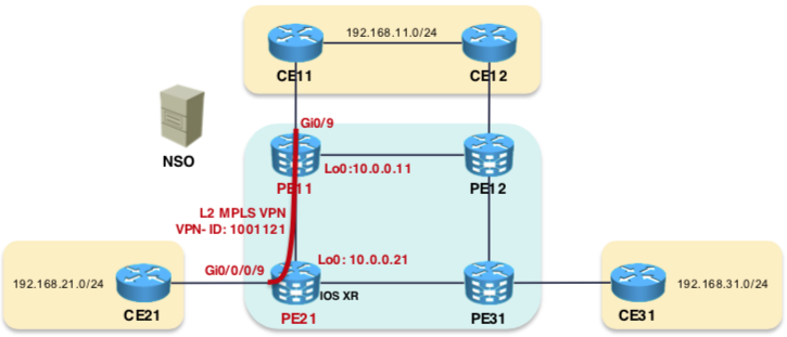
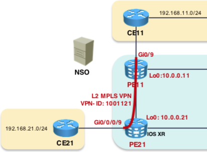
Now Lets create a Service
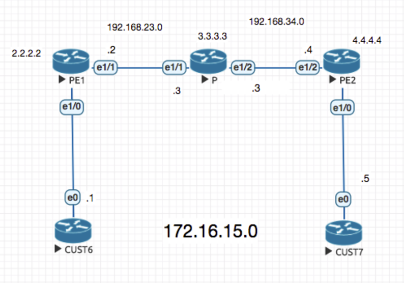
In this activity we will create a simple point to point Layer 2 MPLS VPN
Take a detour a learn a little bit about Layer 2 MPLS VPN , Here is the link to the
blog
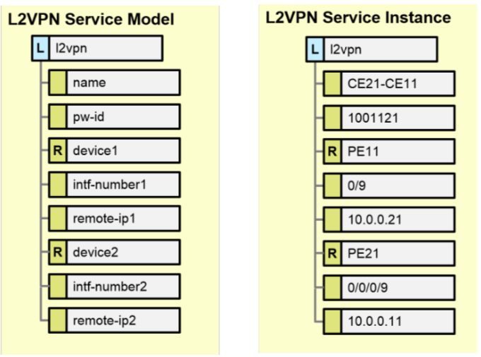
Lets Start with creating an L2 VPN YANG template
In this step a YANG file is created which is basically having the variables to configured in a service . For example in the above VPN configuration in the picture above , the variables would be the VPN-ID,the loopback interfaces , the physicall interfaces on which xconnect is configured . etc .
Look in the Model Below and notice how the real values on the the right map the variables
Create the skeleton
root@cisco-virtual-machine:/opt/ncs/ncs-run/packages/l2vpn/src/yang# cd /opt/ncs/ncs-run/packages/
root@cisco-virtual-machine:/opt/ncs/ncs-run/packages# ncs-make-package --service-skeleton template l2vpn
root@cisco-virtual-machine:/opt/ncs/ncs-run/packages# ls
cisco-ios  cisco-ios-xr  l2vpn
Now edit the l2vpn.yang file and put in the data below
More Details on the YANG file format on the other blog but for now proceed.
module l2vpn {
  namespace "http://com/example/l2vpn";
  prefix l2vpn;

  import ietf-inet-types { prefix inet; }
  import tailf-ncs { prefix ncs; }
  import tailf-common { prefix tailf; }

  augment "/ncs:services" {
    list l2vpn {
      key "name";
      unique "pw-id";
      uses ncs:service-data;
      ncs:servicepoint "l2vpn";
      leaf name {
        tailf:info "Service Instance Name";
        type string;
      }
      leaf pw-id {
        tailf:info "Unique Pseudowire ID";
        mandatory true;
        type uint32 {
          range "1..4294967295";
        }
      }
      leaf device1 {
        tailf:info "PE Router1";
        mandatory true;
        type leafref {
          path "/ncs:devices/ncs:device/ncs:name";
        }
      }
      leaf intf-number1 {
        tailf:info "GigabitEthernet Interface ID";
        mandatory true;
        type string {
          pattern "[0-9]{1,2}(/[0-9]{1,2}){1,4}";
        }
      }
      leaf remote-ip1 {
        tailf:info "Loopback0 IP Address of Remote PE (10.0.0.X)";
        mandatory true;
        type inet:ipv4-address {
          pattern "10\\.0\\.0\\.[0-9]+";
        }
      }
      leaf device2 {
        tailf:info "PE Router2";
        mandatory true;
        type leafref {
          path "/ncs:devices/ncs:device/ncs:name";
        }
      }
      leaf intf-number2 {
        tailf:info "GigabitEthernet Interface ID";
        mandatory true;
        type string {
          pattern "[0-9]{1,2}(/[0-9]{1,2}){1,4}";
        }
      }
      leaf remote-ip2 {
        tailf:info "Loopback0 IP Address of Remote PE (10.0.0.X)";
        mandatory true;
        type inet:ipv4-address {
          pattern "10\\.0\\.0\\.[0-9]+";
        }
      }
    }
  }
}
Note that you can correct the fomating of a YANG file with
pyang -f yang l2vpn.yang >> formatted_output
Validate your YANG file
pyang l2vpn.yang
Change back to the to the src directory and make your build
root@cisco-virtual-machine:/opt/ncs/ncs-run/packages/l2vpn/src/yang# cd ..
root@cisco-virtual-machine:/opt/ncs/ncs-run/packages/l2vpn/src# make
mkdir -p ../load-dir
/opt/ncs/bin/ncsc  `ls l2vpn-ann.yang  > /dev/null 2>&1 && echo "-a l2vpn-ann.yang"` \
              -c -o ../load-dir/l2vpn.fxs yang/l2vpn.yang
root@cisco-virtual-machine:/opt/ncs/ncs-run/packages/l2vpn/src#
Now reload the pluging in NCS
root@cisco-virtual-machine:/opt/ncs/ncs-run# ncs_cli -u admin -C

admin connected from 192.168.1.12 using ssh on cisco-virtual-machine
admin@ncs#
admin@ncs#
admin@ncs# packages reload
reload-result {
    package cisco-ios
    result true
}
reload-result {
    package cisco-iosxr
    result true
}
reload-result {
    package l2vpn
    result true
}
admin@ncs#
Check CLI for the new l2vpn commands
admin@ncs(config)# services l2vpn ?
Possible completions:
  Service Instance Name  range
admin@ncs(config)# services l2vpn
You still cannot start provisioning services. A service template is missing and it will be created in the next task.
Now Lets create a Device Template based on the Actual CLI configuration
Following are the “real” CLI commands used in a typical MPLS L2 VPN configuration. We will configure this on the NSO and then work on templating the config with variables.
Cisco IOS
interface GigabitEthernet0/9
  xconnect 10.0.0.21 1001121 encapsulation mpls
Cisco IOS XR
l2vpn
 xconnect group ACME
  p2p CE11-to-CE21
   interface GigabitEthernet0/0/0/9
   neighbor 10.0.0.11 pw-id 1001121
  !
!
interface GigabitEthernet0/0/0/9
 l2transport
!
Now configure the devices in question as per the provided values in the picture below . Note : We will not apply the configuration but just get the XML output and abort
admin@ncs(config)# show configuration
devices device PE11
 config
  ios:interface GigabitEthernet0/9
   xconnect 10.0.0.21 1001121 encapsulation mpls
  exit
 !
!
devices device PE21
 config
  cisco-ios-xr:interface GigabitEthernet 0/0/0/9
   l2transport
   exit
  exit
  cisco-ios-xr:l2vpn
   xconnect group GROUP
    p2p CE11-to-CE21
     interface GigabitEthernet0/0/0/9
     neighbor 10.0.0.11 pw-id 1001121
     exit
    exit
   exit
  exit
 !
!
Use the commit dry-run outformat xml command to retrieve the XML version of the configuration above.
admin@ncs(config)# commit dry-run outformat xml
result-xml {
    local-node {
        data <devices xmlns="http://tail-f.com/ns/ncs">
               <device>
                 <name>PE11</name>
                 <config>
                   <interface xmlns="urn:ios">
                     <GigabitEthernet>
                       <name>0/9</name>
                       <xconnect>
                         <address>10.0.0.21</address>
                         <vcid>1001121</vcid>
                         <encapsulation>mpls</encapsulation>
                       </xconnect>
                     </GigabitEthernet>
                   </interface>
                 </config>
               </device>
               <device>
                 <name>PE21</name>
                 <config>
                   <interface xmlns="http://tail-f.com/ned/cisco-ios-xr">
                     <GigabitEthernet>
                       <id>0/0/0/9</id>
                       <l2transport/>
                     </GigabitEthernet>
                   </interface>
                   <l2vpn xmlns="http://tail-f.com/ned/cisco-ios-xr">
                     <xconnect>
                       <group>
                         <name>GROUP</name>
                         <p2p>
                           <name>CE11-to-CE21</name>
                           <interface>
                             <name>GigabitEthernet0/0/0/9</name>
                           </interface>
                           <neighbor>
                             <address>10.0.0.11</address>
                             <pw-id>1001121</pw-id>
                           </neighbor>
                         </p2p>
                       </group>
                     </xconnect>
                   </l2vpn>
                 </config>
               </device>
             </devices>
    }
}
Now go to $NCS_DIR/ncs-run/packages/l2vpn/templates and edit the l2vpn-template.xml file
In the template below we will put the config generated above for each device. Twice in a section as the device could be either IOS or IOSXR.
<config-template xmlns="http://tail-f.com/ns/config/1.0"
                 servicepoint="l2vpn">
  <devices xmlns="http://tail-f.com/ns/ncs">


    <!-- DEVICE1 -->
    <device>
      <name>{/device1}</name>
      <config>

        <!-- DEVICE1/IOS -->

        <!-- DEVICE1/IOS-XR -->

      </config>
    </device>


    <!-- DEVICE2 -->
    <device>
      <name>{/device2}</name>
      <config>

        <!-- DEVICE1/IOS -->

        <!-- DEVICE1/IOS-XR -->

      </config>
    </device>


  </devices>
</config-template>
So after putting the XML Data generated as a part of Dry run in the above template the XML file now looks like this
<?xml version="1.0" encoding="UTF-8"?>
<config-template xmlns="http://tail-f.com/ns/config/1.0"                 servicepoint="l2vpn">
  <devices xmlns="http://tail-f.com/ns/ncs">
    <!-- DEVICE1 -->
    <device>
      <name>{/device1}</name>
      <config>
        <!-- DEVICE1/IOS -->

        <interface xmlns="urn:ios">
          <GigabitEthernet>
            <name>0/9</name>
            <xconnect>
              <address>10.0.0.21</address>
              <vcid>1001121</vcid>
              <encapsulation>mpls</encapsulation>
            </xconnect>
          </GigabitEthernet>
        </interface>

        <!-- DEVICE1/IOS-XR -->

        <interface xmlns="http://tail-f.com/ned/cisco-ios-xr">
          <GigabitEthernet>
            <id>0/0/0/9</id>
            <l2transport/>
          </GigabitEthernet>
        </interface>
        <l2vpn xmlns="http://tail-f.com/ned/cisco-ios-xr">
          <xconnect>
            <group>
              <name>GROUP</name>
              <p2p>
                <name>CE11-to-CE21</name>
                <interface>
                  <name>GigabitEthernet0/0/0/9</name>
                </interface>
                <neighbor>
                  <address>10.0.0.11</address>
                  <pw-id>1001121</pw-id>
                </neighbor>
              </p2p>
            </group>
          </xconnect>
        </l2vpn>
      </config>
    </device>

    <!-- DEVICE2 -->
    <device>
      <name>{/device2}</name>
      <config>
        <!-- DEVICE2/IOS -->

        <interface xmlns="urn:ios">
          <GigabitEthernet>
            <name>0/9</name>
            <xconnect>
              <address>10.0.0.21</address>
              <vcid>1001121</vcid>
              <encapsulation>mpls</encapsulation>
            </xconnect>
          </GigabitEthernet>
        </interface>

        <!-- DEVICE2/IOS-XR -->

        <interface xmlns="http://tail-f.com/ned/cisco-ios-xr">
          <GigabitEthernet>
            <id>0/0/0/9</id>
            <l2transport/>
          </GigabitEthernet>
        </interface>
        <l2vpn xmlns="http://tail-f.com/ned/cisco-ios-xr">
          <xconnect>
            <group>
              <name>GROUP</name>
              <p2p>
                <name>CE11-to-CE21</name>
                <interface>
                  <name>GigabitEthernet0/0/0/9</name>
                </interface>
                <neighbor>
                  <address>10.0.0.11</address>
                  <pw-id>1001121</pw-id>
                </neighbor>
              </p2p>
            </group>
          </xconnect>
        </l2vpn>


      </config>
    </device>
  </devices>
</config-template>
Now in the next step we will replace the hardcoded value in the XML above to variables so that it is templated.
Here is the file after the values are templated
<?xml version="1.0" encoding="UTF-8"?>
<config-template xmlns="http://tail-f.com/ns/config/1.0"                 servicepoint="l2vpn">
  <devices xmlns="http://tail-f.com/ns/ncs">
    <!-- DEVICE1 -->
    <device tags="nocreate">
      <name>{/device1}</name>
      <config tags="merge">
        <!-- DEVICE1/IOS -->

        <interface xmlns="urn:ios">
          <GigabitEthernet>
            <name>{/intf-number1}</name>
            <xconnect>
              <address>{/remote-ip1}</address>
              <vcid>{/pw-id}</vcid>
              <encapsulation>mpls</encapsulation>
            </xconnect>
          </GigabitEthernet>
        </interface>

        <!-- DEVICE1/IOS-XR -->

        <interface xmlns="http://tail-f.com/ned/cisco-ios-xr">
          <GigabitEthernet>
            <id>{/intf-number1}</id>
            <l2transport/>
          </GigabitEthernet>
        </interface>
        <l2vpn xmlns="http://tail-f.com/ned/cisco-ios-xr">
          <xconnect>
            <group>
              <name>GROUP</name>
              <p2p>
                <name>{/name}</name>
                <interface>
                  <name>GigabitEthernet{/intf-number1}</name>
                </interface>
                <neighbor>
                  <address>{/remote-ip1}</address>
                  <pw-id>{/pw-id}</pw-id>
                </neighbor>
              </p2p>
            </group>
          </xconnect>
        </l2vpn>
      </config>
    </device>

    <!-- DEVICE2 -->
    <device tags="nocreate">
      <name>{/device2}</name>
      <config tags="merge">
        <!-- DEVICE1/IOS -->

        <interface xmlns="urn:ios">
          <GigabitEthernet>
            <name>{/intf-number2}</name>
            <xconnect>
              <address>{/remote-ip2}</address>
              <vcid>{/pw-id}</vcid>
              <encapsulation>mpls</encapsulation>
            </xconnect>
          </GigabitEthernet>
        </interface>

        <!-- DEVICE1/IOS-XR -->

        <interface xmlns="http://tail-f.com/ned/cisco-ios-xr">
          <GigabitEthernet>
            <id>{/intf-number2}</id>
            <l2transport/>
          </GigabitEthernet>
        </interface>
        <l2vpn xmlns="http://tail-f.com/ned/cisco-ios-xr">
          <xconnect>
            <group>
              <name>GROUP</name>
              <p2p>
                <name>{/name}</name>
                <interface>
                  <name>GigabitEthernet{/intf-number2}</name>
                </interface>
                <neighbor>
                  <address>{/remote-ip2}</address>
                  <pw-id>{/pw-id}</pw-id>
                </neighbor>
              </p2p>
            </group>
          </xconnect>
        </l2vpn>


      </config>
    </device>
  </devices>
</config-template>
After saving the above file (/opt/ncs/ncs-run/packages/l2vpn/templates) perform a reload of the packages for NCS
admin@ncs# packages reload
reload-result {
    package cisco-ios
    result true
}
reload-result {
    package cisco-iosxr
    result true
}
reload-result {
    package l2vpn
    result true
}
You should now see more options in the L2VPN Service configuration
admin@ncs(config)# services l2vpn CE11-CE21 ?
Possible completions:
  check-sync           Check if device config is according to the service
  commit-queue
  deep-check-sync      Check if device config is according to the service
  device1              PE Router1
  device2              PE Router2
  get-modifications    Get the data this service created
  intf-number1         GigabitEthernet Interface ID
  intf-number2         GigabitEthernet Interface ID
  log
  pw-id                Unique Pseudowire ID
  re-deploy            Run/Dry-run the service logic again
  reactive-re-deploy   Reactive redeploy of service logic
  remote-ip1           Loopback0 IP Address of Remote PE (10.0.0.X)
  remote-ip2           Loopback0 IP Address of Remote PE (10.0.0.X)
  touch                Touch a service
  un-deploy            Undo the effects of this service
  <cr>
Now deploy the service on the routers in the example
admin@ncs(config)# services l2vpn CE11-CE21 pw-id 1001121 device1 PE11 intf-number1 0/9 remote-ip1 10.0.0.21 device2 PE21 intf-number2 0/0/0/9 remote-ip2 10.0.0.11
admin@ncs(config-l2vpn-CE11-CE21)# commit dry-run
cli {
    local-node {
        data  devices {
                  device PE11 {
                      config {
                          ios:interface {
             +                GigabitEthernet 0/9 {
             +                    xconnect {
             +                        address 10.0.0.21;
             +                        vcid 1001121;
             +                        encapsulation mpls;
             +                    }
             +                }
                          }
                      }
                  }
                  device PE21 {
                      config {
                          cisco-ios-xr:interface {
             +                GigabitEthernet 0/0/0/9 {
             +                    l2transport {
             +                    }
             +                }
                          }
                          cisco-ios-xr:l2vpn {
                              xconnect {
             +                    group GROUP {
             +                        p2p CE11-CE21 {
             +                            interface GigabitEthernet0/0/0/9;
             +                            neighbor 10.0.0.11 1001121;
             +                        }
             +                    }
                              }
                          }
                      }
                  }
              }
              services {
             +    l2vpn CE11-CE21 {
             +        pw-id 1001121;
             +        device1 PE11;
             +        intf-number1 0/9;
             +        remote-ip1 10.0.0.21;
             +        device2 PE21;
             +        intf-number2 0/0/0/9;
             +        remote-ip2 10.0.0.11;
             +    }
              }
    }
}
After the above is finally commited by a commit you see the actuall configuration changes on the device by the following command :
admin@ncs(config)# show full-configuration devices device PE11
devices device PE11
 address   127.0.0.1
 port      10022
 ssh host-key ssh-rsa
  key-data "AAAAB3NzaC1yc2EAAAADAQABAAABAQC8dMrFKaxMJWsJZgHkV+LJqqIbxxUB3ntam9BpES32\n86fDHaMQPHqVxMqXGnTP5kJYHL8y5hmR9q6pcdDCZ+eCoLZZnjZvWu74Osqa1Av2e9NW4yoX\nSheaj3GRur7roLcv0rzenpipKUnlzv6Hl9yw2nA3E1FFljMEZZ2yhaZ0j8JlMEIvSVEmGbzD\nATlnblrW0sgAVPtC0ssoEwBQaRX8iicN3GsDcMpW7/mkVfkROws1JTO5C/UC0Um0bL5miJ7z\n+eKvIZiRY80pBKTjY17e8L4iKOvwwPV9VdlHB3ePJuZw4NNqcd5m2NuiqtnGBlu0MIxeoIhu\nnTa+xAyqoKH3"
 !
 authgroup default
 device-type cli ned-id cisco-ios
 state admin-state unlocked
 config
  no ios:service pad
  ios:ip vrf my-forward
   bgp next-hop Loopback 1
  !
  ios:ip community-list 1 permit
  ios:ip community-list 2 deny
  ios:ip community-list standard s permit
Also verify the current service demployment by the following command :
  admin@ncs# show running-config services l2vpn
  services l2vpn CE11-CE21
   pw-id        1001121
   device1      PE11
   intf-number1 0/9
   remote-ip1   10.0.0.21
   device2      PE21
   intf-number2 0/0/0/9
   remote-ip2   10.0.0.11
  !

  admin@ncs# show running-config services l2vpn | display xpath
  /services/l2vpn:l2vpn[name='CE11-CE21']/pw-id 1001121
  /services/l2vpn:l2vpn[name='CE11-CE21']/device1 PE11
  /services/l2vpn:l2vpn[name='CE11-CE21']/intf-number1 0/9
  /services/l2vpn:l2vpn[name='CE11-CE21']/remote-ip1 10.0.0.21
  /services/l2vpn:l2vpn[name='CE11-CE21']/device2 PE21
  /services/l2vpn:l2vpn[name='CE11-CE21']/intf-number2 0/0/0/9
  /services/l2vpn:l2vpn[name='CE11-CE21']/remote-ip2 10.0.0.11

  admin@ncs# show running-config services l2vpn | tab
                               INTF     REMOTE              INTF     REMOTE
  NAME       PW ID    DEVICE1  NUMBER1  IP1        DEVICE2  NUMBER2  IP2
  ------------------------------------------------------------------------------
  CE11-CE21  1001121  PE11     0/9      10.0.0.21  PE21     0/0/0/9  10.0.0.11
You can undeploy a service :
services l2vpn CE11-to-CE31 un-deploy
Check to see if the service is still present in the NSO configuration database.
show full-configuration services l2vpn
Check the state of the un-deployed service instance using the check-sync command.
services l2vpn CE11-to-CE31 check-sync
Now re-deploy the service instance to make it operational again
services l2vpn CE11-to-CE31 re-deploy
Check the status
services l2vpn CE11-to-CE31 check-sync
Assign Service Instances to Customers
In this task, you will modify the service model (The YANG Model) to include the assignment of service instances to customers.
leaf customer {
  tailf:info "Customer name";
  type leafref {
path "/ncs:customers/ncs:customer/ncs:id"; }
}
After adding the above , make the file and reload packeges.
You will now be able to assign Customer to the Services
Entering configuration mode terminal
admin@ncs(config)# services l2vpn CE11-to-CE31 customer ?
Description: Customer name
Possible completions:
  ACME
admin@ncs(config)# services l2vpn CE11-to-CE31 customer ACME
admin@ncs(config-l2vpn-CE11-to-CE31)# top
admin@ncs(config)# commit

admin@ncs# show running-config services l2vpn CE11-to-CE31
services l2vpn CE11-to-CE31
 customer     ACME
 pw-id        1011131
 device1      PE11
 intf-number1 0/7
 remote-ip1   10.0.0.21
 device2      PE31
 intf-number2 0/0/0/7
 remote-ip2   10.0.0.11
Creating a Custom Auth Group for “Real Cisco Devices”
Get the Remote Device Ready for Connection
enable password cisco
username vikassri pass cisco

line vty 0 4
 password cisco
 login local
 transport input telnet
!
1.Go to the following screen (can be done via CLI)
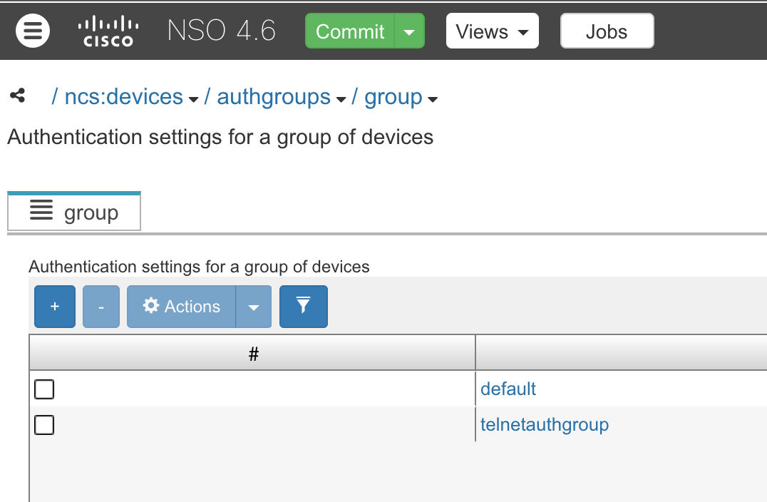 2.Define the Parameters and the users
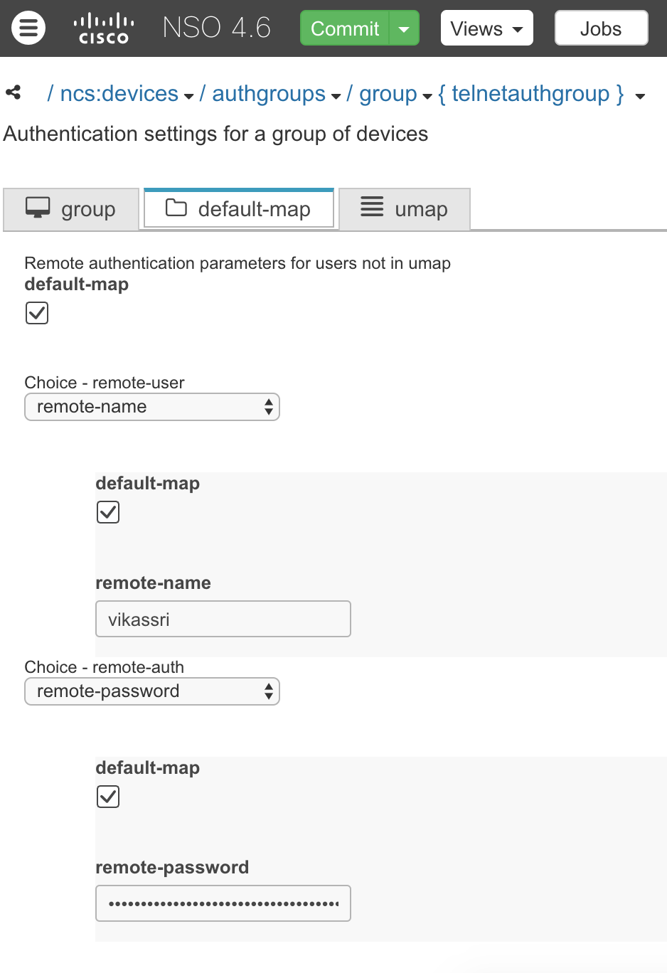 3.Create a local user
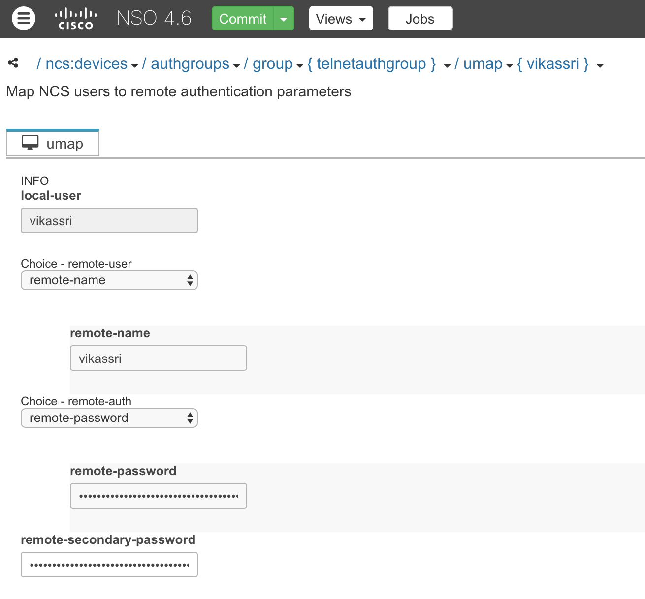
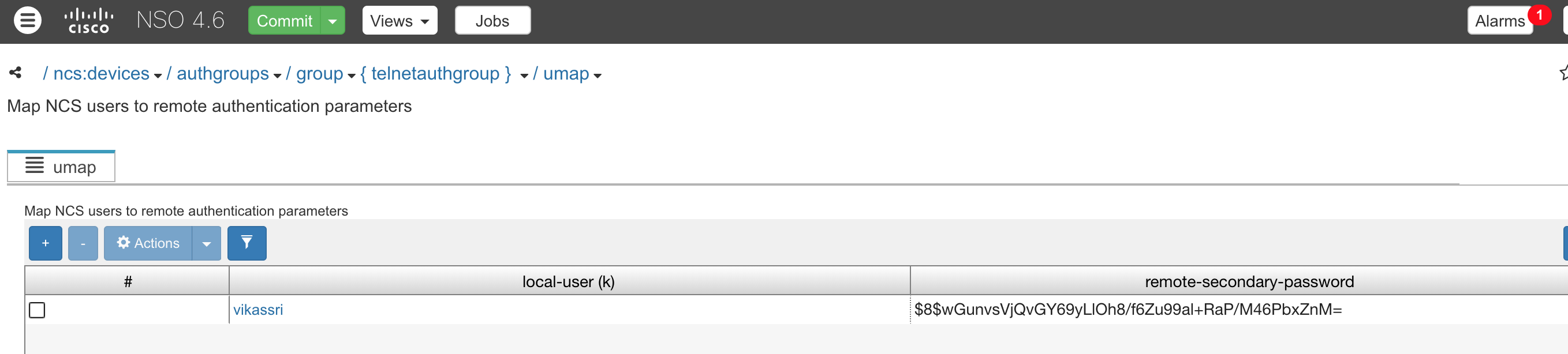 4.User Parameters
CLI Way of doing the above :
# devices authgroups group JUN_Auth default-map remote-name root remote-password cisco
# devices device JUN1 address 10.66.77.39 port 22 authgroup JUN_Auth device-type netconf
# devices device JUN1 state admin-state unlocked
# devices device JUN2 connect
$ devices device JUN2 sync-from
Now once you have the above configuration done , try adding OSPF configuration for the device from CLI and update !
You Can Install Custom Commands at /ncs-run/scripts/command
cisco@NCS:~/ncs-run/scripts/command$ more show-trace #!/bin/sh
set -e
newline=cat
while [ $# -gt 0 ]; do
    case "$1" in
        --command)
            cat << EOF
begin command
  modes: oper
  styles: c i j
  cmdpath: show trace
  help: Show the contents of trace log files
  more: true
end
EOF
 exit
;; list)
        cd /home/cisco/ncs-run/logs/
        ls -1 *.trace
        exit
        ;;
    file)
        cd /home/cisco/ncs-run/logs/
        more $2
        exit
        ;;
*)
break
;; esac
                                Step 3
Step 4
shift done
echo Specify a trace log file to display.
echo Usege:
echo show trace list ... lists trace log files
echo show trace file \<file\> ... displays the selected log file
exit
And then load the above command in NSO
admin@ncs# script reload
/opt/ncs/ncs-run/scripts: ok
You can verify the activity by
admin@ncs# show trace file ned-cisco-ios-PE11.trace
>> 28-Jan-2016::01:58:14.909 CLI CONNECT to PE11-127.0.0.1:10101 as admin (Trace=false)
<< 28-Jan-2016::01:58:15.178 CONNECTED 0
>> 28-Jan-2016::01:58:15.179 IS_ALIVE 0
<< 28-Jan-2016::01:58:15.181 IS_ALIVE true
>> 28-Jan-2016::01:58:46.807 CLOSE 0: (Pool: discard) << 28-Jan-2016::01:58:46.817 CLOSED
admin@ncs#
Note that only the scripts created in the above format will be availaible in the clie after
scripts reload. The script below will not be availaible; As it is not the NSO script format.
Another example of the Script
#!/bin/sh
{ ncs_cli -u admin -C<< EOF;
config
customers customer $1 rank 128 status active
commit
exit no-confirm
exit
EOF
}
if [ $? != 0 ]; then echo 'create-customer: script failed'; exit 1; fi
NCS Troubleshooting commands
ncs --stop
ncs --foreground -v
Service Model Optimisation
In the service deployed earlier for the MPLS VPN the user had to manually find out from somewhere else the interface numbers and the IP Address of the remote end before typing it in. This introdcues risk for errors.
We can optimise the service model by collecting that information programmaticaly .
Here are some of the optimisations which we would follow:
- Place circuits in a list called
linkwith amaxandminelements to2. - Link to the devices interface so that they can be selected instead of typed in !
- Automatically retrieve the other PE’s loopback address.
Alright so lets tackle the task 1 above .
Optimized files for the exercise
optimized.l2vpn.yang
module l2vpn {
  namespace "http://com/example/l2vpn";
  prefix l2vpn;

  import ietf-inet-types {
    prefix inet;
  }
  import tailf-ncs {
    prefix ncs;
  }
  import tailf-common {
    prefix tailf;
  }

  import tailf-ned-cisco-ios {
    prefix ios;
  }
  import tailf-ned-cisco-ios-xr {
    prefix cisco-ios-xr;
  }

  augment "/ncs:services" {
    list l2vpn {
      key "name";
      unique "pw-id";
      uses ncs:service-data;
      ncs:servicepoint "l2vpn";
      leaf name {
        tailf:info "Service Instance Name";
        mandatory true;
        type string;
      }
      leaf pw-id {
        tailf:info "Unique Pseudowire ID";
        mandatory true;
        type uint32 {
          range "1..4294967295";
        }
      }
      list link {
        tailf:info "Attachment Circuits";
        min-elements 2;
        max-elements "2";
        key "device";
        leaf device {
          tailf:info "PE Router";
          mandatory true;
          type leafref {
            path "/ncs:devices/ncs:device/ncs:name";
          }
        }
        container ios {
          when "/ncs:devices/ncs:device[ncs:name=current()/../device]/ncs:device-type/ncs:cli/ncs:ned-id='ios-id:cisco-ios'" {
            tailf:dependency "../device";
            tailf:dependency "/ncs:devices/ncs:device/ncs:device-type";
          }
          leaf intf-number {
            tailf:info "GigabitEthernet Interface ID";
            mandatory true;
            type leafref {
              path "deref(../../device)/../ncs:config/ios:interface/ios:GigabitEthernet/ios:name";

            }
          }
        }
        container iosxr {
          when "/ncs:devices/ncs:device[ncs:name=current()/../device]/ncs:device-type/ncs:cli/ncs:ned-id='cisco-ios-xr-id:cisco-ios-xr'" {
            tailf:dependency "../device";
            tailf:dependency "/ncs:devices/ncs:device/ncs:device-type";
          }
          leaf intf-number {
            tailf:info "GigabitEthernet Interface ID";
            mandatory true;
            type leafref {
              path "deref(../../device)/../ncs:config/cisco-ios-xr:interface/cisco-ios-xr:GigabitEthernet/cisco-ios-xr:id";
            }
          }
        }
        leaf remote-ip {
          tailf:info "Loopback0 IP Address of Remote PE (10.0.0.X)";
          mandatory true;
          type inet:ipv4-address {
            pattern "10\\.0\\.0\\.[0-9]+";
          }
        }
      }
    }
  }
}
optimized.l2vpn-template.xml
<?xml version="1.0" encoding="UTF-8"?>
<config-template xmlns="http://tail-f.com/ns/config/1.0" servicepoint="l2vpn">
  <devices xmlns="http://tail-f.com/ns/ncs">
    <device tags="nocreate">
      <name>{/link[1]/device}</name>
      <config tags="merge">
        <interface xmlns="urn:ios" tags="nocreate">
          <GigabitEthernet>
            <name>{/link[1]/ios/intf-number}</name>
            <xconnect tags="merge">
              <address>{/link[1]/remote-ip}</address>
              <vcid>{/pw-id}</vcid>
              <encapsulation>mpls</encapsulation>
            </xconnect>
          </GigabitEthernet>
        </interface>
        <l2vpn xmlns="http://tail-f.com/ned/cisco-ios-xr" tags="merge">
          <xconnect>
            <group>
              <name>GROUP</name>
              <p2p>
                <name>{/name}</name>
                <interface>
                  <name>GigabitEthernet{/link[1]/iosxr/intf-number}</name>
                  </interface>
                  <neighbor>
                    <address>{/link[1]/remote-ip}</address>
                    <pw-id>{/pw-id}</pw-id>
                  </neighbor>
                </p2p>
              </group>
            </xconnect>
          </l2vpn>
          <interface xmlns="http://tail-f.com/ned/cisco-ios-xr" tags="nocreate">
            <GigabitEthernet>
              <id>{/link[1]/iosxr/intf-number}</id>
              <l2transport/>
            </GigabitEthernet>
          </interface>
        </config>
      </device>
      <device tags="nocreate">
        <name>{/link[2]/device}</name>
        <config tags="merge">
          <interface xmlns="urn:ios" tags="nocreate">
            <GigabitEthernet>
              <name>{/link[2]/ios/intf-number}</name>
              <xconnect tags="merge">
                <address>{/link[2]/remote-ip}</address>
                <vcid>{/pw-id}</vcid>
                <encapsulation>mpls</encapsulation>
              </xconnect>
            </GigabitEthernet>
          </interface>
          <l2vpn xmlns="http://tail-f.com/ned/cisco-ios-xr" tags="merge">
            <xconnect>
              <group>
                <name>GROUP</name>
                <p2p>
                  <name>{/name}</name>
                  <interface>
                    <name>GigabitEthernet{/link[2]/iosxr/intf-number}</name>
                  </interface>
                  <neighbor>
                    <address>{/link[2]/remote-ip}</address>
                    <pw-id>{/pw-id}</pw-id>
                  </neighbor>
                </p2p>
              </group>
            </xconnect>
          </l2vpn>
          <interface xmlns="http://tail-f.com/ned/cisco-ios-xr" tags="nocreate">
            <GigabitEthernet>
              <id>{/link[2]/iosxr/intf-number}</id>
              <l2transport/>
            </GigabitEthernet>
          </interface>
        </config>
      </device>
    </devices>
  </config-template>
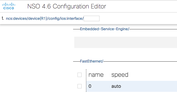
In the above configuration; if you are doing it with simulated routers (Dynamips Based) and if you would like to show the interfaces on the simulated router you will have to modify the
leafrefinintf-numberforcontainer ioslike the following, NOTICE the “FastEthernet”
leaf intf-number {
  tailf:info "FastEthernet Interface ID";
  mandatory true;
  type leafref {
    path "deref(../../device)/../ncs:config/ios:interface/ios:FastEthernet/ios:name";
  }
NOTE the above model can be browsed here
optimized.l2vpn.Makefile
all: fxs
.PHONY: all

# Include standard NCS examples build definitions and rules
include $(NCS_DIR)/src/ncs/build/include.ncs.mk

SRC  = $(wildcard yang/*.yang)
DIRS = ../load-dir
FXS = $(SRC:yang/%.yang=../load-dir/%.fxs)

## Uncomment and patch the line below if you have a dependency to a NED
## or to other YANG files
#YANGPATH += ../../<ned-name>/src/ncsc-out/modules/yang \
# 	../../<pkt-name>/src/yang

YANGPATH +=  /opt/ncs/packages/neds/cisco-ios/src/yang \
             /opt/ncs/packages/neds/cisco-iosxr/src/yang \
             /opt/ncs/packages/neds/cisco-ios/src/ncsc-out/modules/yang \
             /opt/ncs/packages/neds/cisco-iosxr/src/ncsc-out/modules/yang


NCSCPATH   = $(YANGPATH:%=--yangpath %)
YANGERPATH = $(YANGPATH:%=--path %)

fxs: $(DIRS) $(FXS)
.PHONY: fxs

$(DIRS):
	mkdir -p $@


../load-dir/%.fxs: yang/%.yang
	$(NCSC)  `ls $*-ann.yang  > /dev/null 2>&1 && echo "-a $*-ann.yang"` \
             $(NCSCPATH) -c -o $@ $<
clean:
	rm -rf $(DIRS)
.PHONY: clean
NSO 200 Base Yang
module l3mplsvpn {
  namespace "http://com/example/l3mplsvpn";
  prefix l3mplsvpn;

  import ietf-inet-types {
    prefix inet;
  }
  import tailf-ncs {
    prefix ncs;
  }
  import tailf-common {
    prefix tailf;
  }

  augment "/ncs:services" {
    leaf l3mplsvpn-id-cnt {
      description
        "Provides a unique 32-bit number used as VPN instance identifier";
      type uint32;
      default "1";
    }
  }
  augment "/ncs:services" {
    list l3mplsvpn {
      tailf:info "Layer-3 MPLS VPN Service";
      key "vpn-name";
      uses ncs:service-data;
      ncs:servicepoint "l3mplsvpn-servicepoint";
      leaf vpn-name {
        tailf:info "Service Instance Name";
        type string;
      }
      leaf vpn-id {
        tailf:info "Service Instance ID (1 to 65535)";
        type uint32;
      }
      leaf link-id-cnt {
        tailf:info "Provides a unique 32 bit numbers used as a site identifier";
        default "1";
        type uint32;
      }
      leaf customer {
        tailf:info "VPN Customer";
        type leafref {
          path "/ncs:customers/ncs:customer/ncs:id";
        }
      }
      list link {
        tailf:info "PE-CE Attachment Point";
        key "link-name";
        leaf link-name {
          tailf:info "Link Name";
          type string;
        }
        leaf link-id {
          tailf:info "Link ID (1 to 65535)";
          type uint32;
        }
        leaf device {
          tailf:info "PE Router";
          type leafref {
            path "/ncs:devices/ncs:device/ncs:name";
          }
        }
        leaf pe-ip {
          tailf:info "PE-CE Link IP Address";
          type string;
        }
        leaf ce-ip {
          tailf:info "CE Neighbor IP Address";
          type string;
        }
        leaf interface {
          tailf:info "Customer Facing Interface";
          type string;
        }
        leaf routing-protocol {
          tailf:info "Routing option for the PE-CE link";
          type enumeration {
            enum "bgp";
            enum "rip";
          }
        }
      }
    }
  }
}
< An XML Template Dedicated to CE Router >
CE Device

!
interface Loopback0
 no shutdown
 ip address 1.1.1.1 255.255.255.0 <ce_device_lo0_ipaddress>
!

interface GigabitEthernet3 <ce_to_pe_facing_interface>
 no shutdown
 ip address 192.168.12.1 255.255.255.0 <ce_to_pe_facing_interface_ipaddress>
!
router eigrp 100
 network 1.0.0.0 <ce_device_lo0_ipaddress>
 network 192.168.12.0 <ce_to_pe_facing_interface_ipaddress>
!
<?xml version="1.0" encoding="UTF-8"?>
<devices xmlns="http://tail-f.com/ns/ncs">
  <device>
    <name>HQ1</name>
    <config>
      <interface xmlns="urn:ios">
        <Loopback>
          <name>0</name>
          <ip>
            <address>
              <primary>
                <address>9.9.9.9</address>
                <mask>255.255.255.0</mask>
              </primary>
            </address>
          </ip>
        </Loopback>
        <GigabitEthernet>
          <name>1</name>
          <ip>
            <no-address>
              <address xmlns:nc="urn:ietf:params:xml:ns:netconf:base:1.0"                                    nc:operation="delete"/>
            </no-address>
            <address>
              <primary>
                <address>192.168.100.1</address>
                <mask>255.255.255.0</mask>
              </primary>
            </address>
          </ip>
          <shutdown xmlns:nc="urn:ietf:params:xml:ns:netconf:base:1.0"                                 nc:operation="delete"/>
        </GigabitEthernet>
      </interface>
      <router xmlns="urn:ios">
        <eigrp>
          <as-no>100</as-no>
          <network-ip>
            <network>
              <ip>9.9.9.9</ip>
            </network>
            <network>
              <ip>192.168.100.1</ip>
            </network>
          </network-ip>
        </eigrp>
      </router>
    </config>
  </device>
</devices>
< An XML Template Dedicated to PE Router - Side A >
PE Device - Side A

!
ip vrf CUSTOMER-A <customer_name>
 rd 100:1  <value_x:value_y>
 route-target both <value_y:value_x>
!
!
interface GigabitEthernet4 <pe_to_ce_facing_interface>
 no shutdown
 ip vrf forwarding CUSTOMER-A <customer_name>
 ip address 192.168.100.4 255.255.255.0 <ce_to_pe_facing_interface_ipaddress>
!
!
router eigrp 100
 !
 address-family ipv4 vrf CUSTOMER-A <customer_name>
  redistribute bgp 1 metric 1500 400 20 20 1500
  network 192.168.100.4 <ce_to_pe_facing_interface_ipaddress>
  autonomous-system 100
 exit-address-family
!
router bgp 1
 bgp log-neighbor-changes
 neighbor 4.4.4.4 remote-as 1  <side_b_loopback0_ip_address>
 neighbor 4.4.4.4 update-source Loopback0 <side_b_loopback0_ip_address>
 !
 address-family vpnv4
  neighbor 4.4.4.4 activate <side_b_loopback0_ip_address>
  neighbor 4.4.4.4 send-community both <side_b_loopback0_ip_address>
 exit-address-family
 !
 address-family ipv4 vrf CUSTOMER-A <customer_name>
  redistribute eigrp 100
 exit-address-family
!
<?xml version="1.0" encoding="UTF-8"?>
<devices xmlns="http://tail-f.com/ns/ncs">
  <device>
    <name>SP1</name>
    <config>
      <interface xmlns="urn:ios">
        <GigabitEthernet>
          <name>4</name>
          <ip-vrf>
            <ip>
              <vrf>
                <forwarding>CUSTOMER-A</forwarding>
              </vrf>
            </ip>
          </ip-vrf>
          <ip>
            <no-address>
              <address xmlns:nc="urn:ietf:params:xml:ns:netconf:base:1.0"                            nc:operation="delete"/>
            </no-address>
            <address>
              <primary>
                <address>192.168.100.4</address>
                <mask>255.255.255.0</mask>
              </primary>
            </address>
          </ip>
          <shutdown xmlns:nc="urn:ietf:params:xml:ns:netconf:base:1.0"                         nc:operation="delete"/>
        </GigabitEthernet>
      </interface>
      <router xmlns="urn:ios">
        <bgp>
          <as-no>1</as-no>
          <neighbor-tag>
            <neighbor>
              <id>10.10.10.10.</id>
              <remote-as>1</remote-as>
            </neighbor>
          </neighbor-tag>
          <neighbor>
            <id>10.10.10.10</id>
            <update-source>
              <Loopback>0</Loopback>
            </update-source>
          </neighbor>
          <address-family>
            <vpnv4>
              <af>unicast</af>
              <neighbor>
                <id>10.10.10.10</id>
                <activate/>
                <send-community>
                  <send-community-where>both</send-community-where>
                </send-community>
              </neighbor>
            </vpnv4>
          </address-family>
        </bgp>
        <eigrp>
          <as-no>100</as-no>
          <address-family>
            <ipv4>
              <vrf>
                <name>CUSTOMER-A</name>
                <network-ip>
                  <network>
                    <ip>192.168.100.4</ip>
                  </network>
                </network-ip>
              </vrf>
            </ipv4>
          </address-family>
        </eigrp>
      </router>
    </config>
  </device>
</devices>
< An XML Template Dedicated to PE Router - Side B >
PE Device - Side B

!
ip vrf CUSTOMER-A <customer_name>
 rd 100:1  <value_x:value_y>
 route-target both <value_y:value_x>
!
interface GigabitEthernet3 <pe_to_ce_facing_interface>
 no shutdown
 ip vrf forwarding CUSTOMER-A <customer_name>
 ip address 192.168.45.4 255.255.255.0 <ce_to_pe_facing_interface_ipaddress>
!
router eigrp 100
 !
 address-family ipv4 vrf CUSTOMER-A <customer_name>
  redistribute bgp 1 metric 1500 4000 200 10 1500
  network 192.168.45.0 <ce_to_pe_facing_interface_ipaddress>
  autonomous-system 100
 exit-address-family
!
router bgp 1
 bgp log-neighbor-changes
 neighbor 2.2.2.2 remote-as 1 <side_a_loopback0_ip_address>
 neighbor 2.2.2.2 update-source Loopback0 <side_a_loopback0_ip_address>
 !
 address-family vpnv4
  neighbor 2.2.2.2 activate <side_a_loopback0_ip_address>
  neighbor 2.2.2.2 send-community both <side_a_loopback0_ip_address>
 exit-address-family
 !
 address-family ipv4 vrf CUSTOMER-A  <customer_name>
  redistribute eigrp 100
 exit-address-family
!
#NSO 300 - CISCO NETWORK SERVICES ORCHESTRATOR (NSO) ADVANCED DESIGN - PYTHON NOTES
In the Cisco NSO CLI, examine the operational data for the l3mplsvpn package with the show packages package l3mplsvpn command. Verify that the Python component for the l3mplsvpn package is successfully loaded.
admin@ncs# show packages package l3mplsvpn
packages package l3mplsvpn
 package-version 1.0
 description     "Generated Python package"
 ncs-min-version [ 4.6 ]
 python-package vm-name l3mplsvpn
 directory       ./state/packages-in-use/1/l3mplsvpn
 templates       [ l3mplsvpn-template ]
 component main
  `application python-class-name l3mplsvpn.main.Main
  application start-phase phase2`
 oper-status up
The LOG directory is here :
/opt/ncs/ncs-run/logs/ncs-python-vm-l3mplsvpn.log
NEXT STEPS
Make a real router lab for the following and deploy multiple peers between PE1 to PE2 on different ports , and making the configuration changes via NSO
And then start with “Task 1: Service Requirements and Service Model”
Deploy your own blankent OSPF Service on Dynamips routers to make them part of an OSPF Area
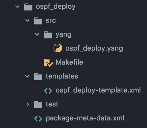
ncs-make-package --service-skeleton template ospf_deploy
Makefile Training https://www.youtube.com/watch?v=Q1Lnp_Xx7z4
NSO Web UI (Learn a little bit)
Create A Directory Structure of Where the YANG is Stored and Where is the Correcpoding Device Template Cofiguration is stored .
Create a Hierarchy Diagram of How the NSO components integrate together for a high leve glane of the over all solution .
Put a place holder to Start documenting vMS / NFV / CSP Solution product portfolio to learn them .
https://www.ansible.com/networks-with-cisco-nso-ansible
Supported NEDS
https://www.cisco.com/c/en/us/products/collateral/cloud-systems-management/network-services-orchestrator/datasheet-c78-734669.html

Subscribe via RSS