
First 7 Days ACI
by Vikas Srivastava
Opinions expressed are solely my own and do not express the views or opinions of my employer.
Notes on “Your First Seven Days Of ACI” - BRKACI-1001 Ciscolive! Session
Day 1 - Why ACI
ACI Advantages
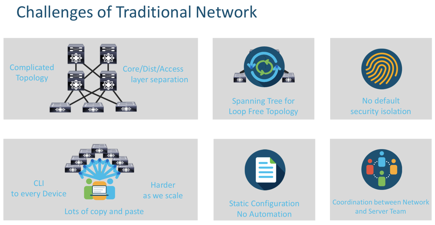
ACI solves the above challenges by providing a simple Leaf/Spine Topology, ECMP which removes the dependency on STP and so on an so forth .
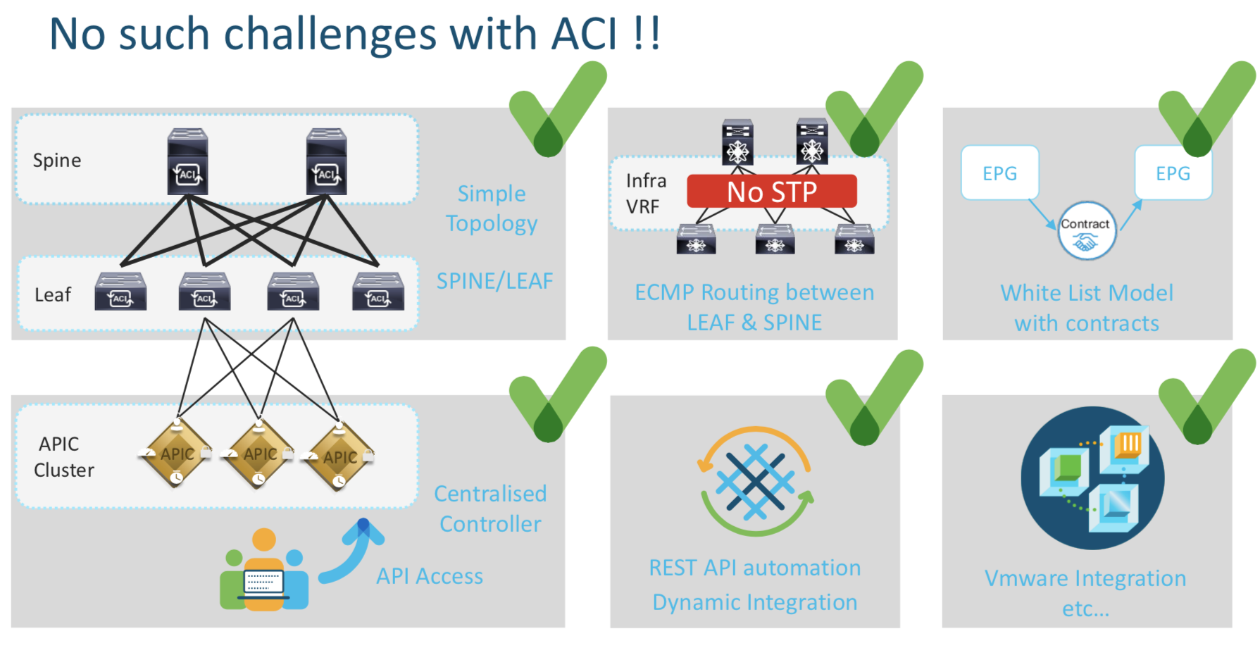
ACI Fabric Discovery Basics

All the internal communication betweek the Spines,Leafs and the APIC happens on the Infra IP Address denoted by red T in the picture above. The reachability provided by this Infra Network is then used to deploy the required L2/L2 config wherever needed on the leafs.
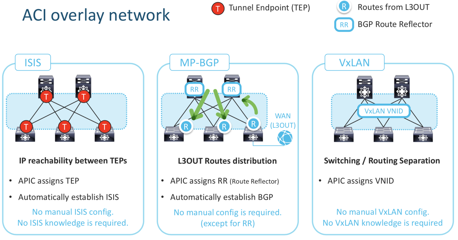
ISIS : This enables IP reachability between TEPs , the APIC assigns the TEP address. ISIS is automatically established and requires no configuration.
MP-BGP : This is L3 Out Configuration . The routes learned via the WAN (L3 Out in the above pic) needs to be “reflected” / “learnt” by other Leafs. Hence the MP-BGP config. Note that the no manual config is required except for the the assignment of RR (Route Reflector)
Using the above two components we build the Underlay Network which builds as the foundation for the overlay network.
APIC Controlled Basics
Basic Details about the Ports on the APIC and the the Leafs/Spine
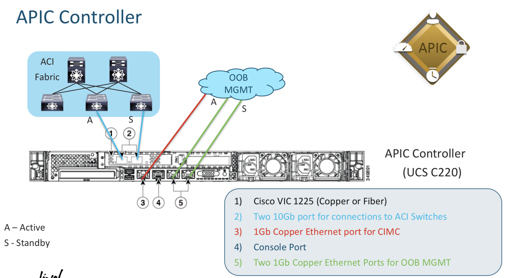
- The Blue cables connect to the Leafs
- The Red cables is the CIMC connection (MGMT)
- The Green Ones are the interfaces on which the Managment Interface of the APIC resides.
Irrespective of what APIC IP Address you connect to via HTTP you see the same data
Its a good idea to ensure all the controller status are in healthy status while troubleshooting an APIC issue
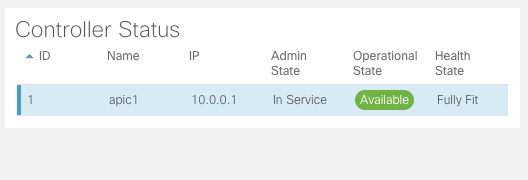
Day 2 - Infrastructure and Policies
Managment Access to Switches
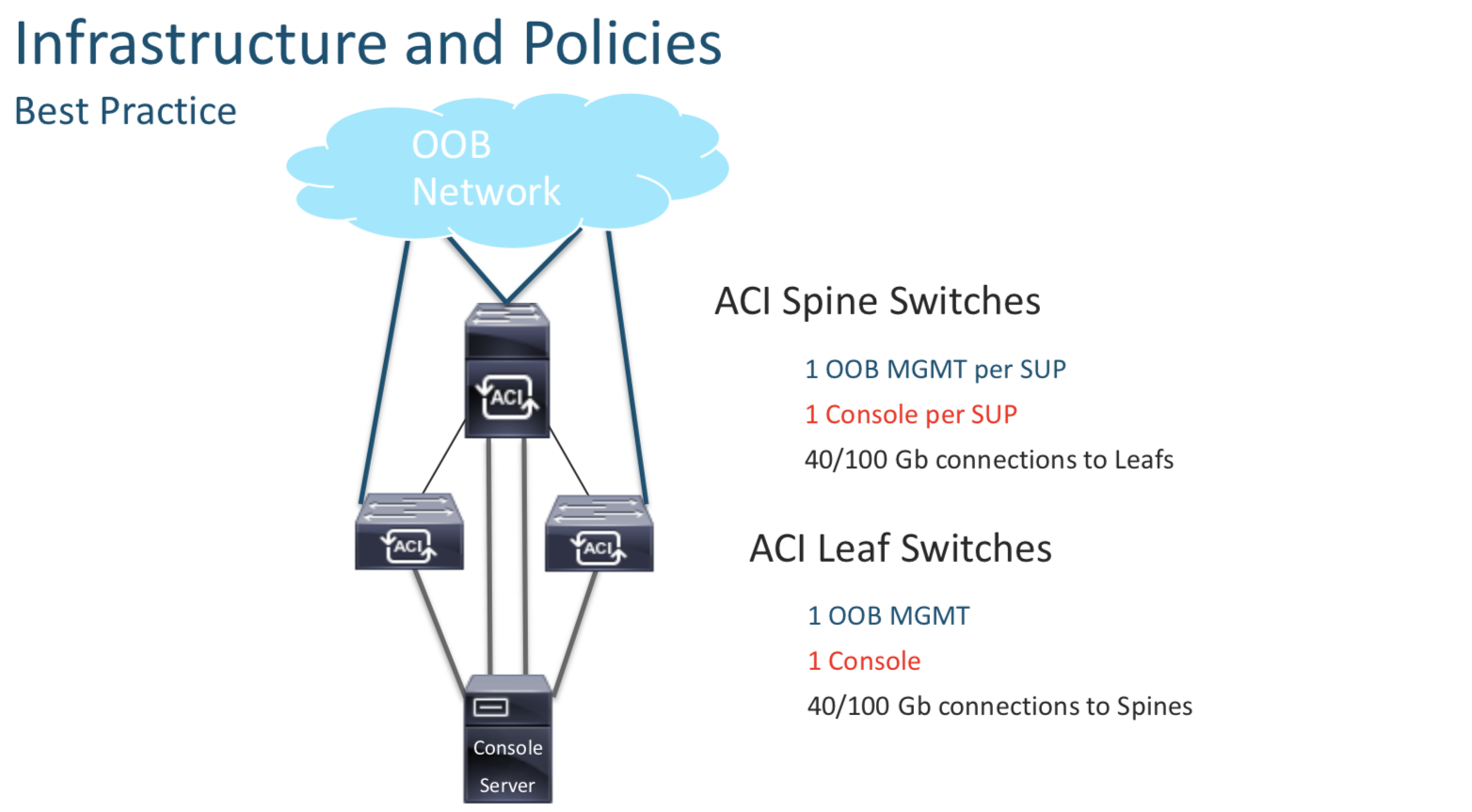
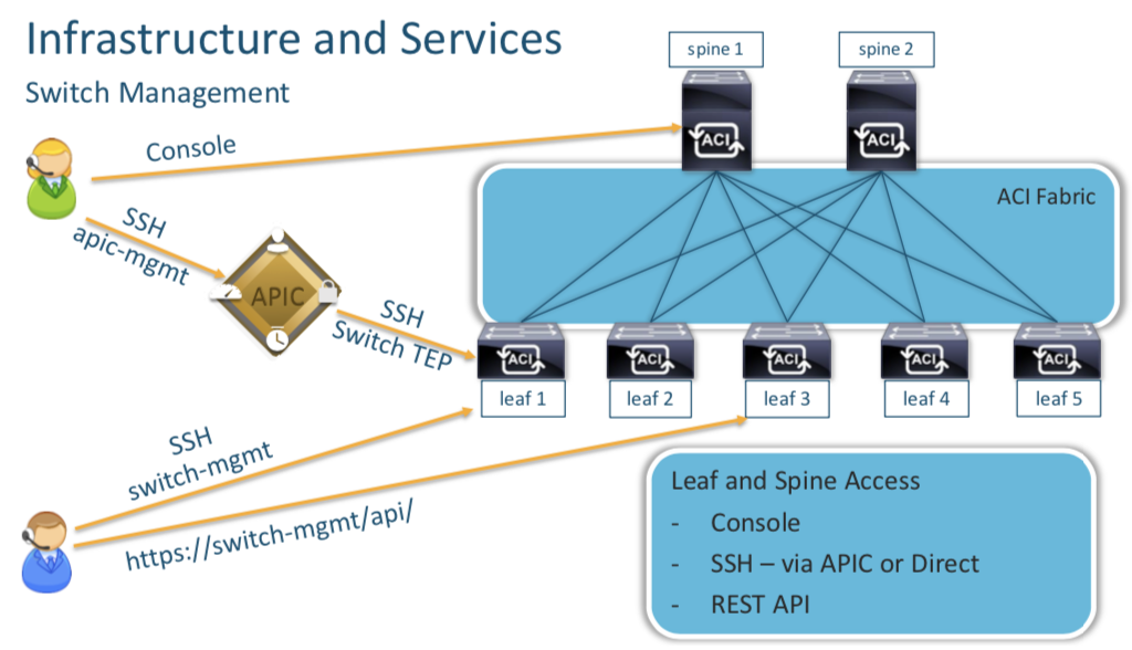
You can access the the Leafs and the Spines using their Console ports on via the APIC (which in turn connects via VTEP addreses). BUT it is advisable to have individual Management IP Addreses assigned to these devices directly (config done after discovery) , so that inc ase we need to access them.
Each device needs their individual mgmt IP (Oulined above) rechability for AAA and NTP
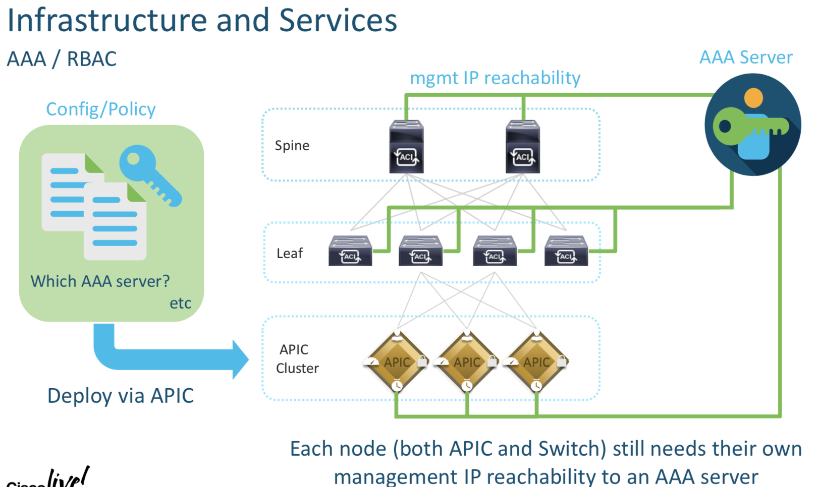
ACI Backups
There are two ways to do backups
- Full Backup
- Snapshots
Capability to compare configuration (Snapshots)
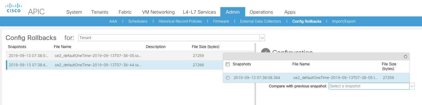
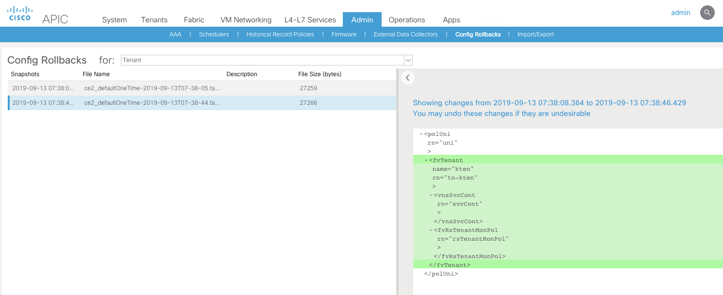
Full Backup
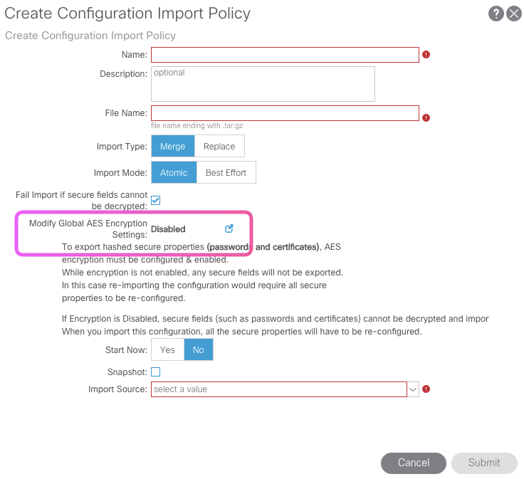
Note in the picture below that when , this setting is disabled during the backup ; the passwords stored for VMWare Integration or any third part integration are NOT exported. If its enabled , the password is exported in an encrypted fashion.
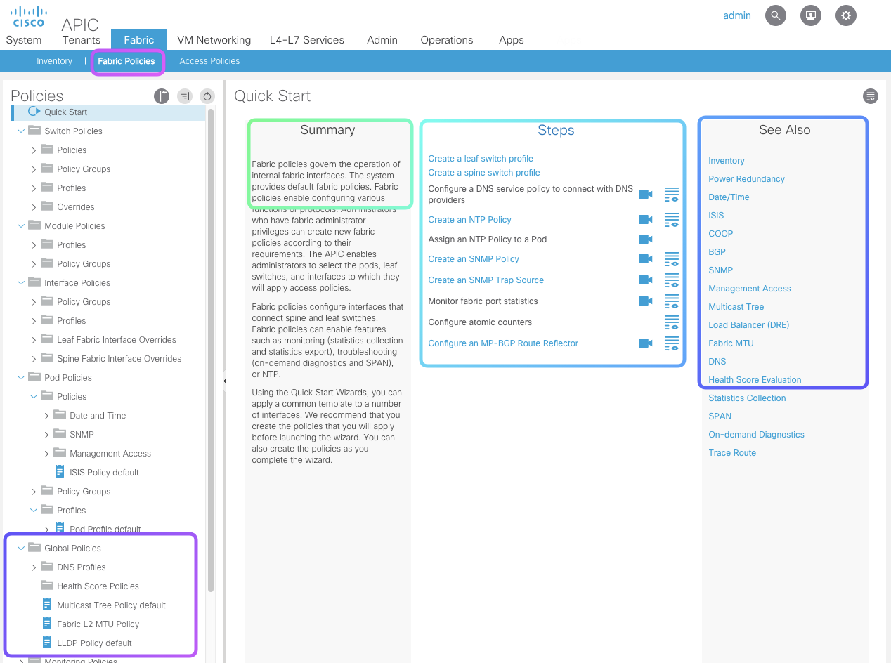
What’s unders the Fabric Tab - This is where you build the UNDERLAY
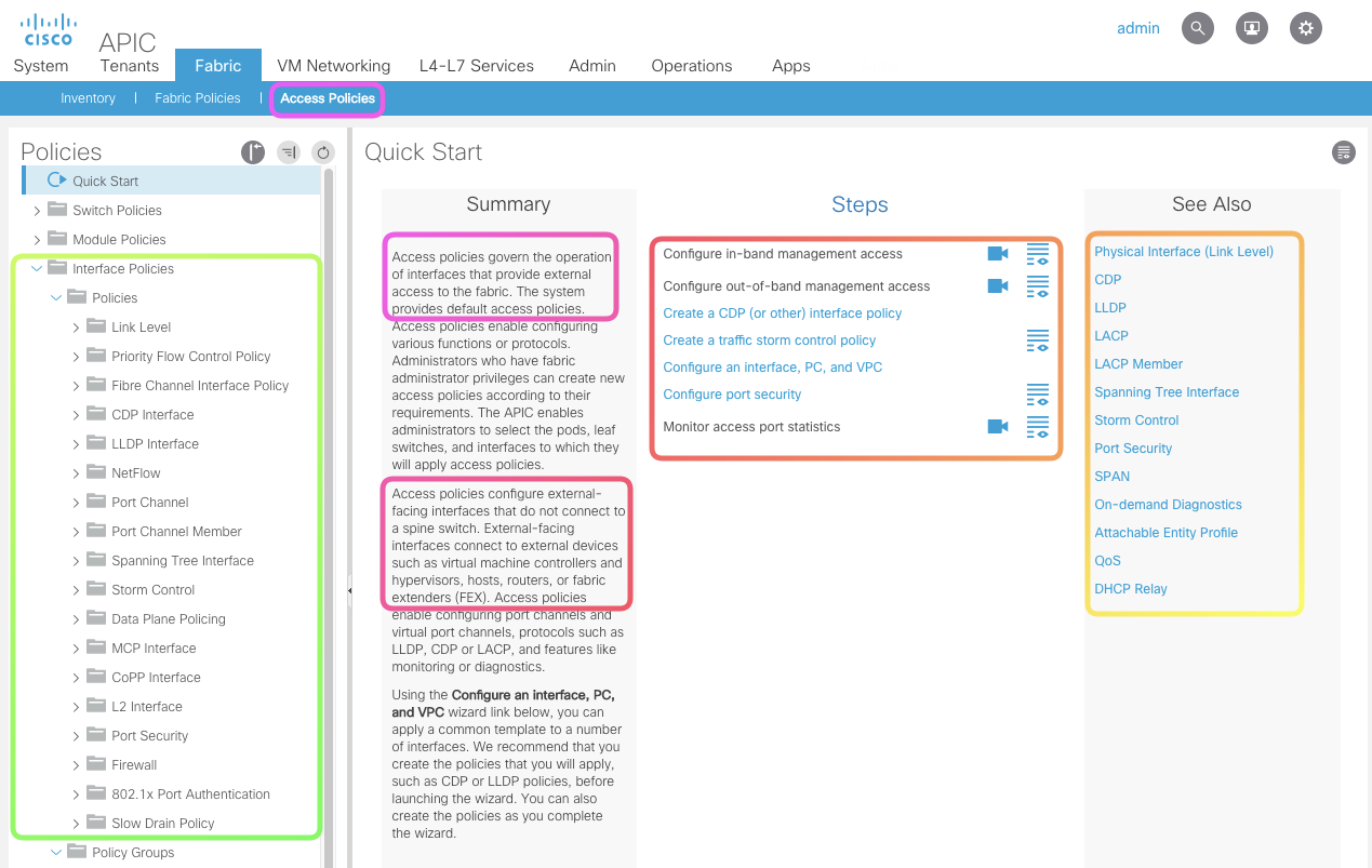
Under Fabric we have Fabric Policies and Access Policies
-
Fabric Policies
Fabric policies govern the operation of internal fabric interfaces. Fabric policies configure interfaces that connect spine and leaf switches. Fabric policies can enable features such as monitoring (statistics collection and statistics export), troubleshooting (on-demand diagnostics and SPAN), or NTP.
-
Access Policies
Access policies govern the operation of interfaces that provide external access to the fabric. Access policies configure external-facing interfaces that do not connect to a spine switch. External-facing interfaces connect to external devices such as virtual machine controllers and hypervisors, hosts, routers, or fabric extenders (FEX).
Whats unders the Tenants Tab - This is where you build the OVERLAY
-
Tenant Policies
Tenant Policies: Its is more about configuration related to EPG/BD/VRF. A tenant is a logical container or a folder for application policies. This container can represent an actual tenant, an organization, or a domain or can just be used for the convenience of organizing information.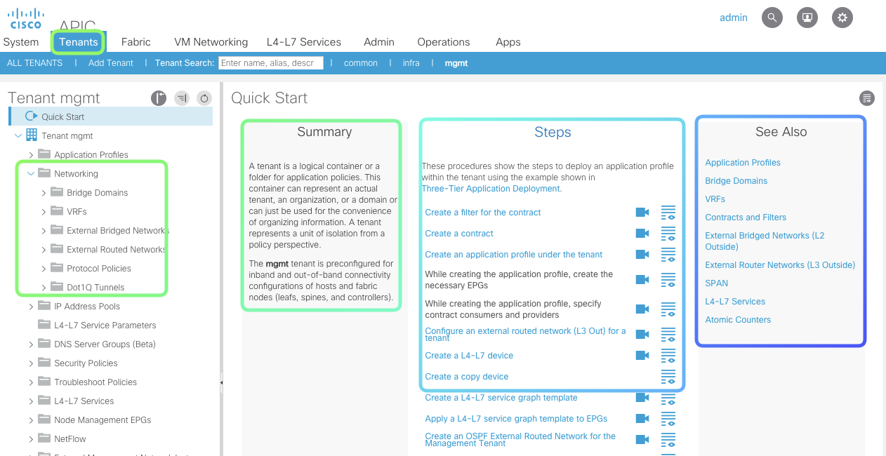
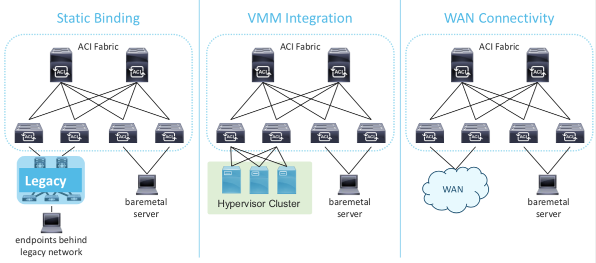
We have three types of configuration in Tenant Policies
-
Static Binding
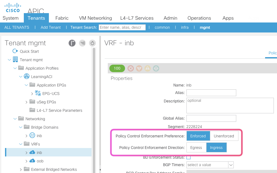
Policy Control Enfrocementdefines if the any contracts policies will be enforced or not.Policy Control Directiondefines which direction it is applied.An Example of a Static Path Binding Config
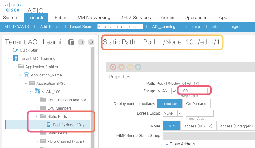 With the above binding configured , you can extend your legacy VLAN configuration to ACI and vice versa
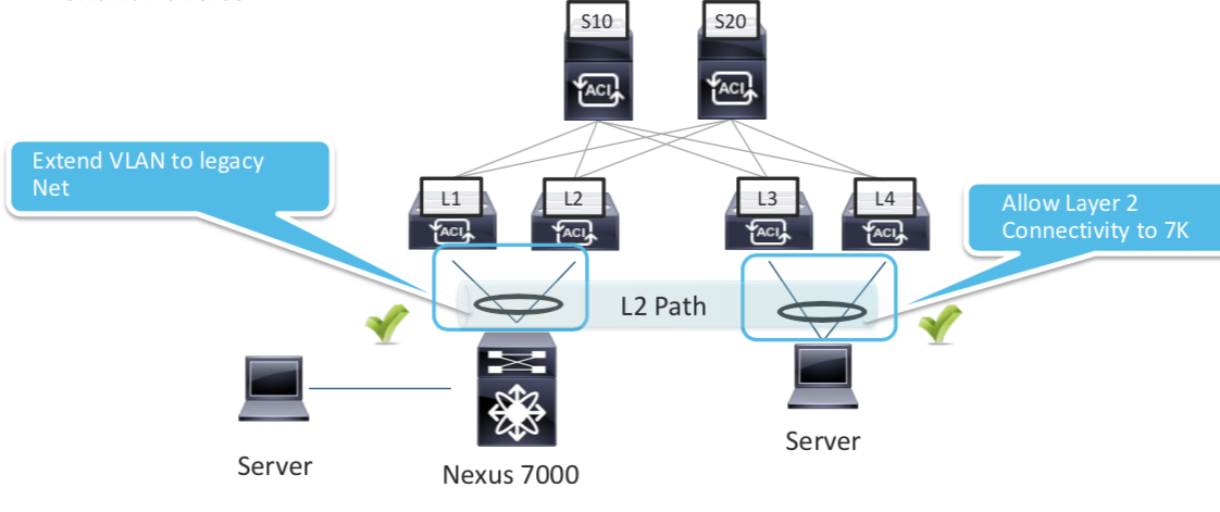 In Picture above VLAN from N7K is extended to ACI
 -
Cisco ACI VMWare Integration
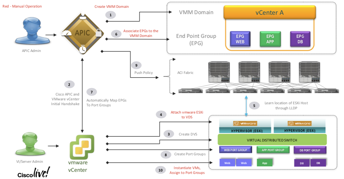
- Step 1. Define the vCenter Domain We are going to talk to .
- Step 2. ACI and VMWare handshake (the communication between APIC and VMWare happens on the Out of Band Network NOT on the INFRA network; We can use the Inband network but is NOT recommened.)
- Step 3. vCenter goes ahead and created a vDS on the VMWare
- Step 4. VMWare Admins Associated the ESXi to the vDS created above
- Step 5. Between the vDS and ACI ;
LLDPhappens , this will tell what VMWare Blade is on what Leaf. - Step 6. Associate the EPGs to the VMMDomain
- Step 7. and Step 8 The EPGs are auto mapped to VMWare Port Groups and are created in VMWare
- Step 9. Now since ACI knows about the Server location based the information learned from LLDP , ACI and now push the policy on the exact switch where needed (Instead of pushing it everywhere).
- So the network path is established above for the VM to ACI
Day 3 - Forwarding Overview
Endpoint
What is an endpoint ?
It’s a combination of MAC address and IP Address.
We can see it on the APIC
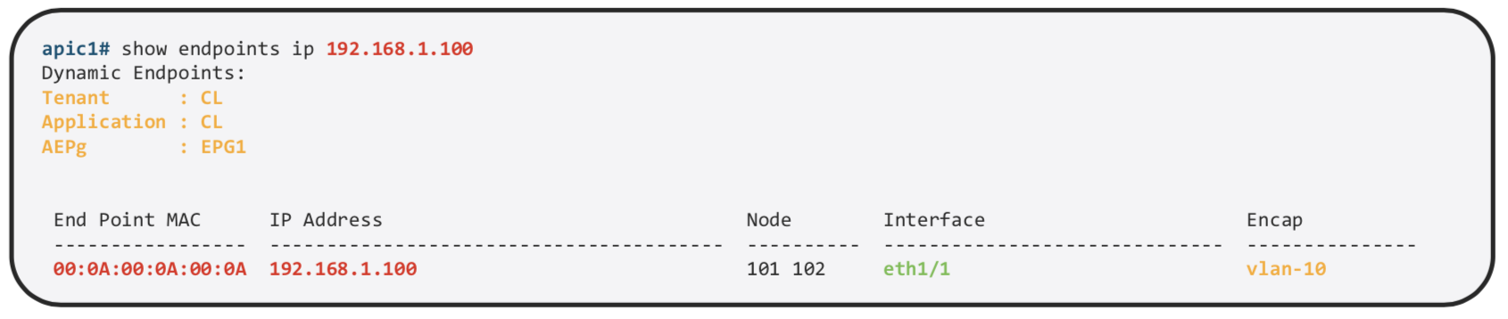
We can find more details about the same on the specific Leaf
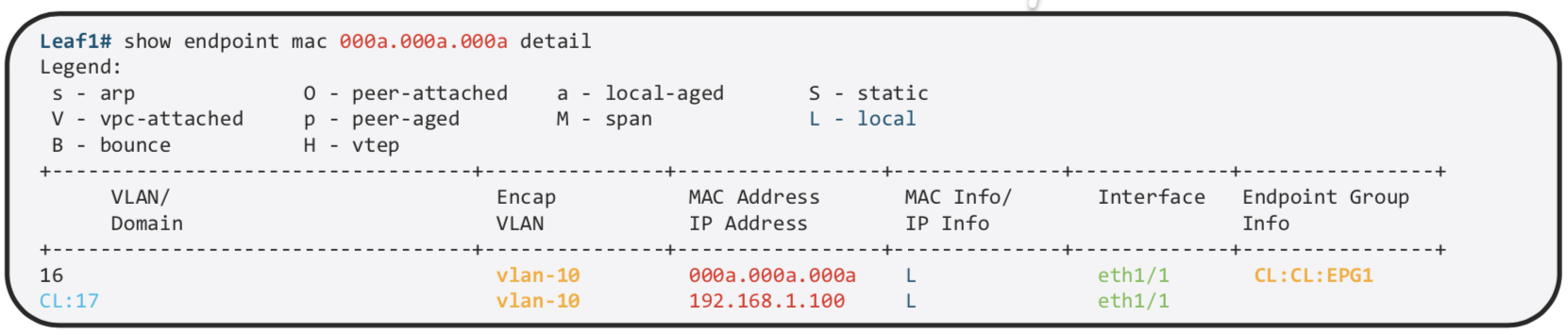
MAC and /32 IP Address are stored in the Endpoint Table
Exception is L3 Out , If we use the same mechanism of learnign all the IP Address , on the MAC address on Nexus router we would have thousand of /32. Other IP Information is used int he Ip Table just as the normal routing. That is the reason why we use arp table for L3 out.
ACI Leafs Can Learn via ARP via 2 Methods
ACI Learns the :
- Source MAC and Source IP during ARP
- A routed frame triggers a Source IP and MAC Address Learning
Pervasive Gateway
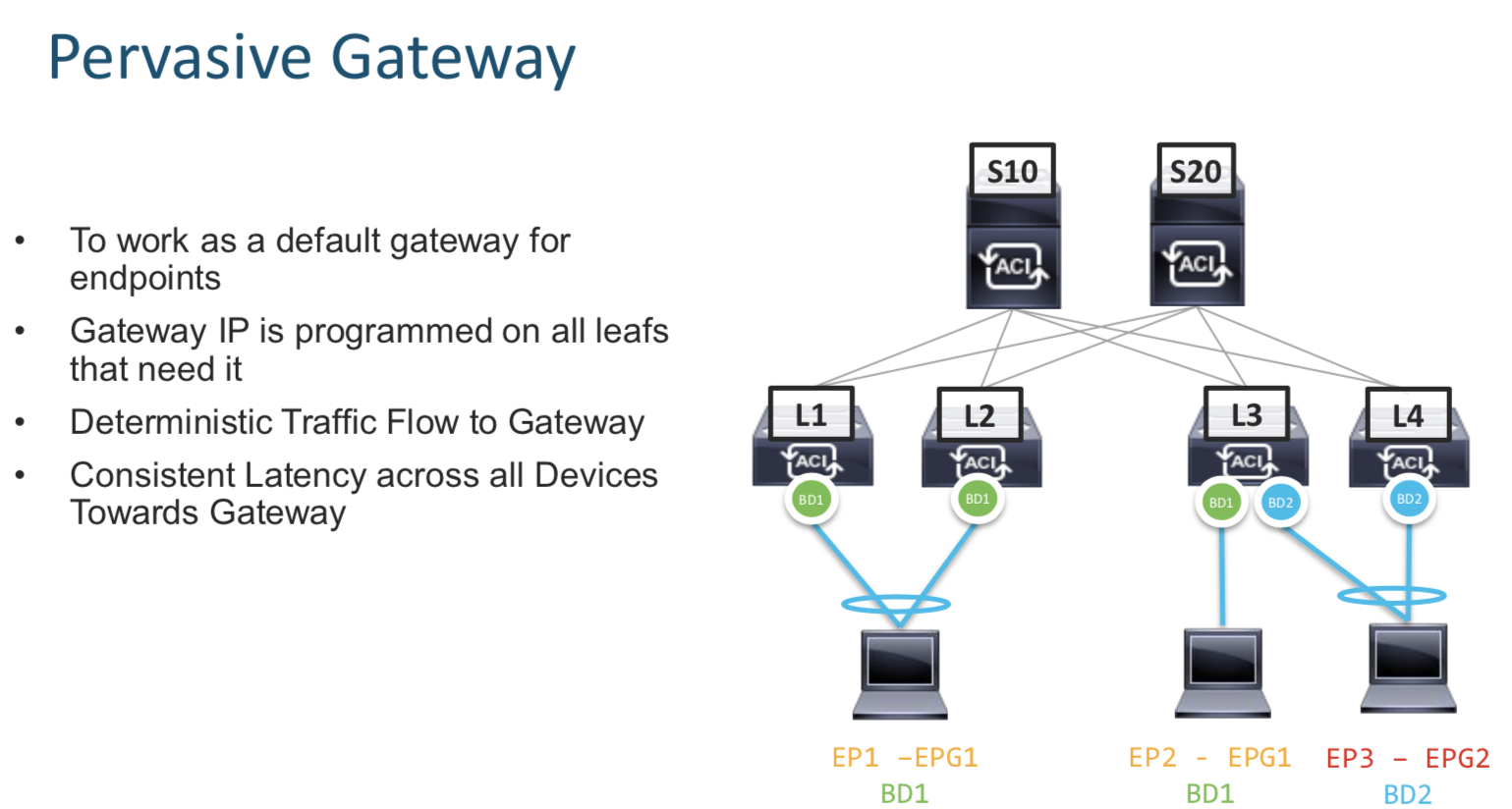
Pervasive gateway means a local gateway residing on every switch for each subnet on that switch.
Proxy Routing
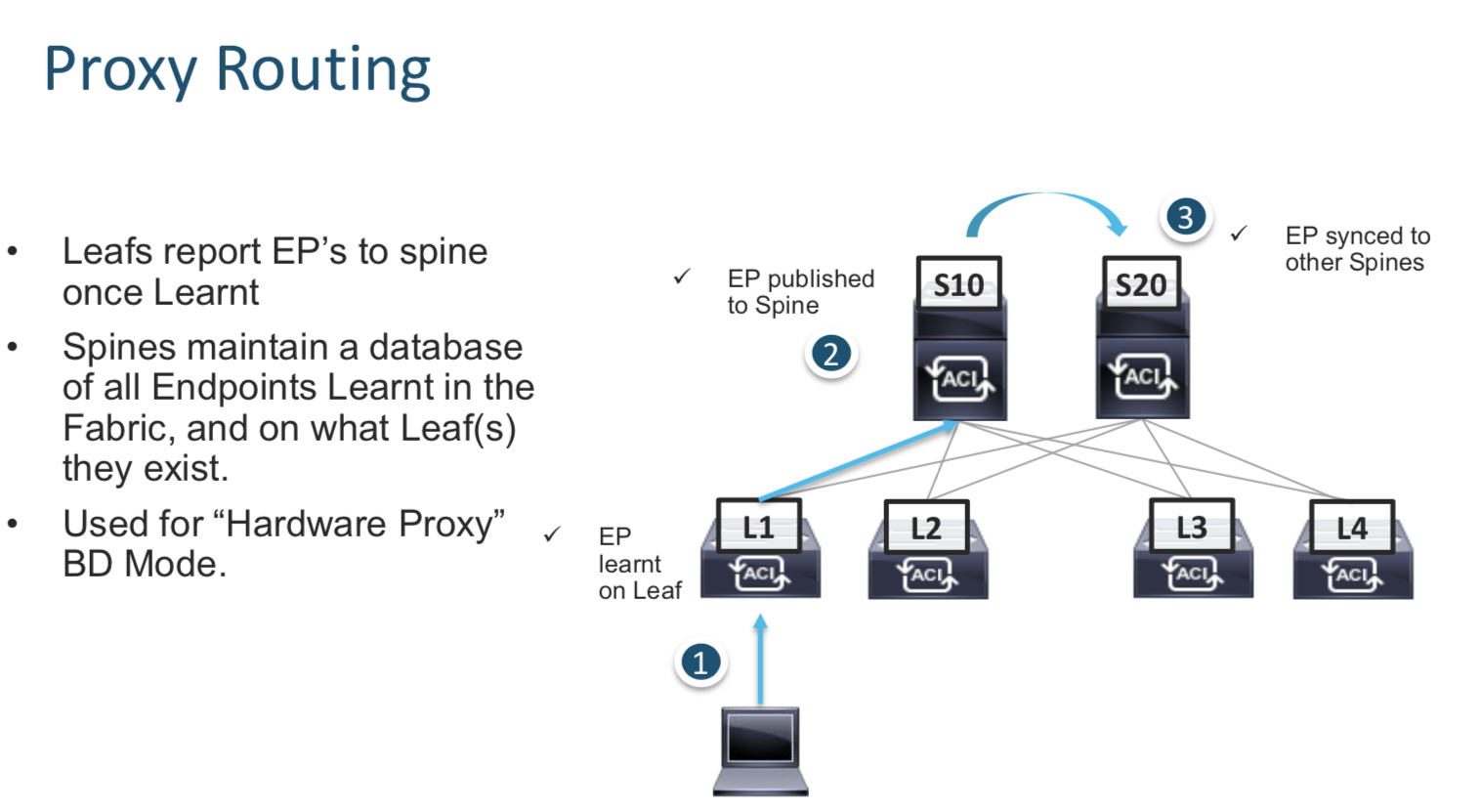
Every endpoint learn by a Leaf is informed to every spine using multicast. This way every SPINE knows about every endpoint in the network.
When Leafs do not know a path to a remote endpoint , they can query the Spine for the same.
Day 4 - Network Centric Migrations
Day 5 - Multi Location Deployments
Day 6 - Troubleshooting Tools
Day 7 - Additional Resources
Digital Learning Topologies
Topology
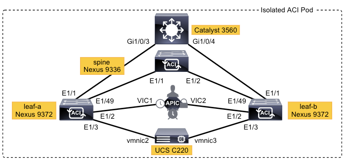
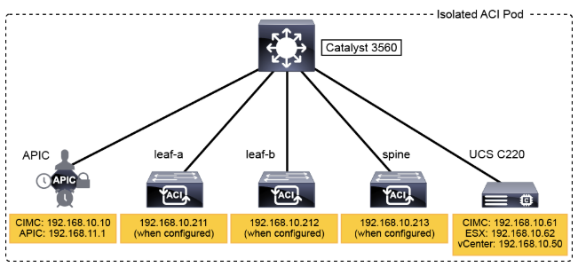
Out of Band Management Access
Lab 1. Explore the Cisco ACI Fabric Inventory
Digital Learning
Fabric: Cisco ACI inventory and configuration point for intra-fabric and access policies
Virtual Networking: Configuration menu for VM Manager interoperability, such as vCenter, Hyper-V, or KVM
L4-L7 Services: Package repository for upper-layer service elements, such as firewalls or load balancers, that can be inserted into the fabric
Admin: Menu for controlling the operation, administration, and maintenance (OAM) aspects
Operations: Menu for visibility, troubleshooting, and capacity profiling
Apps: App center used for deploying applications in the Cisco ACI
The Cisco ACI solution uses an overlay, based on VXLAN, to virtualize the physical infrastructure. This overlay, like most overlays, requires the data path at the edge of the network to map from the tenant end-point address in the packet, also known as its identifier, to the location of the endpoint, also known as its locator. This mapping occurs in a function called a tunnel endpoint (TEP), also known as VXLAN tunnel end point (VTEP). The VTEP addresses are displayed in the INFRASTRUCTURE IP column. The TEP address pool 10.0.0.0/16 has been configured on the Cisco APIC using the initial setup dialog. The APIC assigns the TEP addresses to the fabric switches via DHCP, so the infrastructure IP addresses in your fabric will be different from the figure.
Clickign on the Node provides information on the neigbor and port connectivity
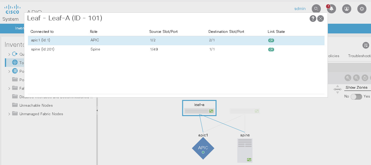
The Link Layer Discovery Protocol (LLDP) is responsible for discovering directly adjacent neighbors. When run between the Cisco APIC and a leaf switch, it precedes three other processes: Tunnel endpoint (TEP) IP address assignment, node software upgrade (if necessary), and the intra-fabric messaging (IFM) process, which is used by the Cisco APIC to push policy to the leaves.
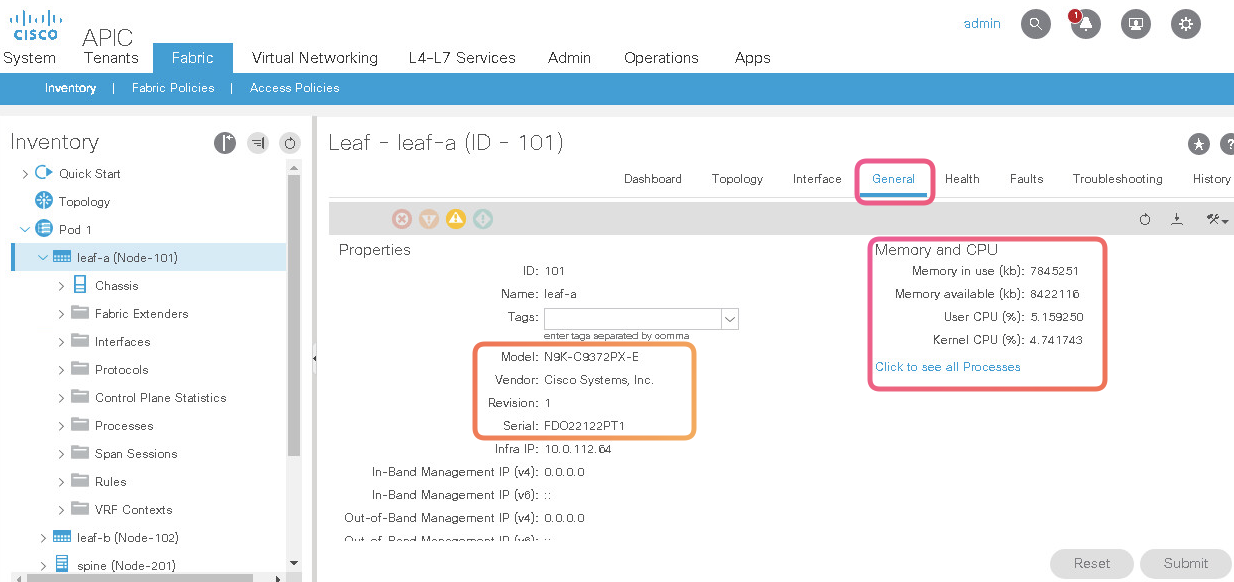
This is where you can see the switch level details
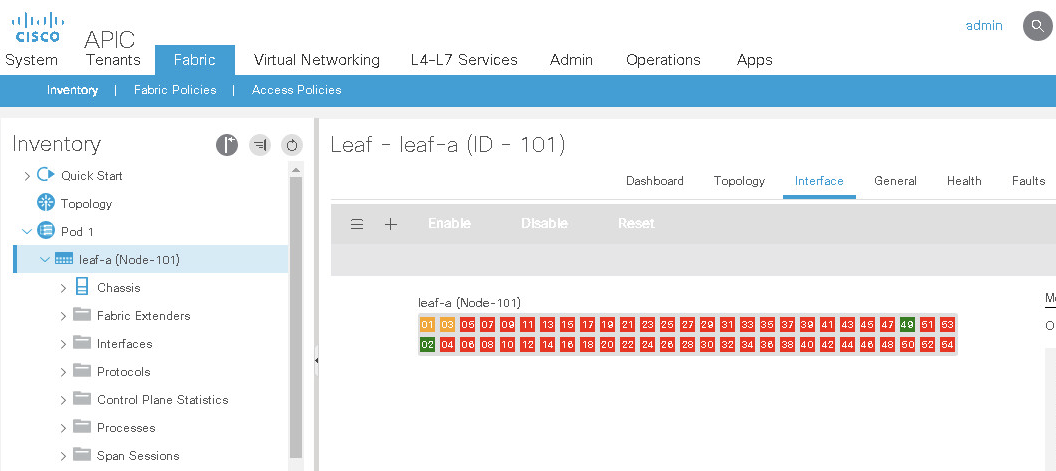
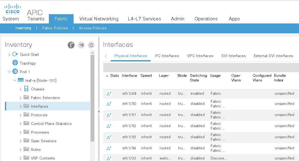
Interface Level Details
ACI Diag is the Diagnostic Command for the APIC
apic1# acidiag -h
usage: acidiag [-h] [-v]
{avread,fnvread,fnvreadex,rvread,rvreadle,crashsuspecttracker,bootother,bootcurr,journal,logs,telemetry,hwcheck,dbgtoken,validateimage,validateng inxconf,version,preservelogs,platform,verifyapic,bond0test,linkflap,touch,run,installer,start,stop,restart,dmestack,dmecore,reboot}
               ...
positional arguments:
{avread,fnvread,fnvreadex,rvread,rvreadle,crashsuspecttracker,bootother,bootcurr,journal,logs,telemetry,hwcheck,dbgtoken,validateimage,validatenginxconf,version,preservelogs,platform,verifyapic,bond0test,linkflap,touch,run,installer,start          ,stop,restart,dmestack,dmecore,reboot}
                        sub-command help
    avread              read appliance vector
    fnvread             read fabric node vector
    fnvreadex           read fabric node vector (extended mode)
    rvread              read replica vector
    rvreadle            read replica leader summary
    crashsuspecttracker
                        read crash suspect tracker state
    bootother           on next boot, boot other Linux Partition, and display
                        updated /etc/grub.conf
    bootcurr            on next boot, boot current Linux Partition, and
                        display updated /etc/grub.conf
    journal             Contents of journal logs
    logs                show log history
    telemetry           enable/disable telemetry
    hwcheck             Quick check of APIC Hardware
    dbgtoken            show debug token
    validateimage       validate image
    validatenginxconf   validate nginx conf
    version             show ISO version
    preservelogs        stash away logs in preparation for hard reboot
    platform            show platform
    verifyapic          run apic installation verify command
    bond0test           ==SUPPRESS==
    linkflap            flap a link
    touch               touch special files
    run                 run specific commands and capture output
    installer           installer
    start               start a service
    stop                stop a service
    restart             restart a service
    reboot              reboot

optional arguments:
  -h, --help            show this help message and exit
  -v, --verbose         verbose
apic1# acidiag fnvread
ID   Pod ID   Name     Serial Number  IP Address      Role   State   LastUpdMsgId
----------------------------------------------------------------------------------
101    1      leaf-a   FDO21351F7L   10.0.128.66/32   leaf   active   0
102    1      leaf-b   FDO21351F9A   10.0.128.64/32   leaf   active   0
201    1      spine    FDO214111Q5   10.0.128.65/32   spine  active   0

Total 3 nodes
Cisco APIC Version (3.1) allows you to configure the system and view the configuration through the CLI.
apic1# conf t
apic1(config)# sh run
# Command: show running-config
  aaa banner 'Application Policy Infrastructure Controller'
  aaa authentication login console
    exit
<... output omitted ...>
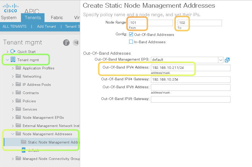
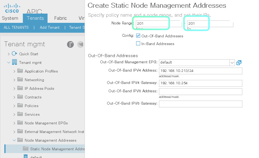
Static Out of Band management Address
*Notice that you assign a subnet , and IP Addresses are choosen from that block**
Result of Above configuration
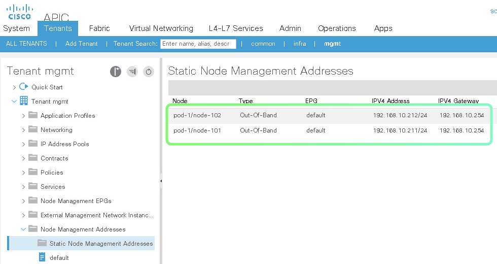
To assign to the ONLY ONE devide put the same number twice
leaf-a# show lldp neighbors
Capability codes:
  (R) Router, (B) Bridge, (T) Telephone, (C) DOCSIS Cable Device
  (W) WLAN Access Point, (P) Repeater, (S) Station, (O) Other
Device ID            Local Intf      Hold-time  Capability  Port ID
3560-x.dc.local       Eth1/1          120        BR          Gi1/0/3
apic1                 Eth1/2          120                    eth2-1
spine                 Eth1/49         120        BR          Eth1/1
Total entries displayed: 3
Removing OOB Management Address Does not affect the capabilit to SSH from APIC to Leaf as this happens with the inra network which ACI had seatup
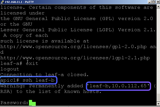
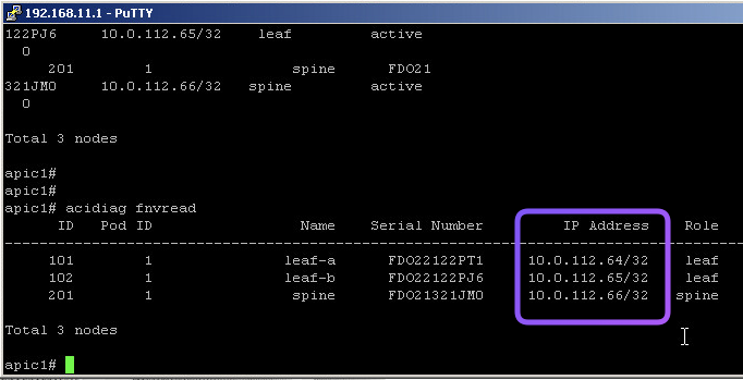
This is where you can validate the OOB Management address of a specific Leaf/Spine
Lab 2. Configuring Port Channel
In this Lab2 we wil configure the following scenario
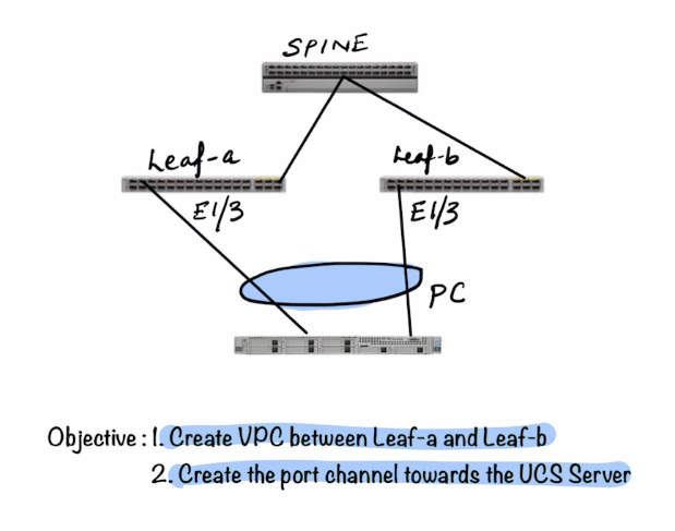
The following components are to be configured (show in purple)
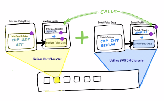
High Level Steps
-
Configuring the Port Character
- Enable the CDP in a CDP interface policy that is named
CDP-Enabled. - Configure an interface policy (
LLDP-Disabled), with LLDP disabled. - Configure a port channel policy, named
PC-Policy, with a static port channel mode. Ensure that you haveStatic Channel—Mode On
Notice above that you have separate config item named “Port Channel Policy” in ACI
- Configure vPC Interface Policy Group - An interface policy group gathers multiple interface policies into one set. A vPC interface policy group gathers the policies with the purpose of activating them on a vPC interface bundle. In your topology, the hypervisor is connected to the leaves in a redundant fashion that allows a vPC deployment. You will configure a vPC policy group for your hypervisor. Name is
IPG-VPC-ESXand add everything you created above within it.
What’s happenign int he above step is that you are defining the characteristics of what a vPC member port would look like
- Create a Leaf Interface Profile name
InterProf-ESX - Select the Interfaces as
1/3 - Select the
Interface Policy Groupcreated above int hePort Charachtersection :IPG-VPC-ESX
- Enable the CDP in a CDP interface policy that is named
-
Configuring the Switch Character
- Create a Leaf Profile -
LeafProfile-ESX, add both-leaves 101 and 102 - Associate the Interface Selector
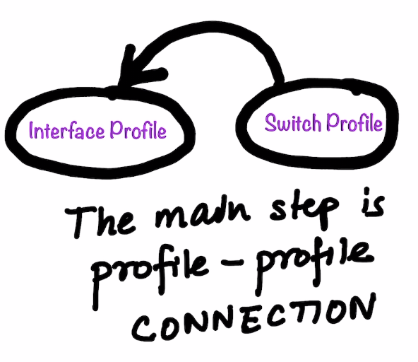
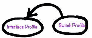
Interface-Profile-ESXThis is the actual step where theInterface ProfileandSwitch Profileconnect.
- Create a Leaf Profile -
-
Finally Configure vPC between Leafs
- Review/Look at the VPC Default Domain
Fabric > Access Policies > Switch Policies > Policies > VPC Domain. - Add both leaf switches to the vPC security policy
Fabric > Access Policies > Switch Policies > Policies > Virtual Port Channel default. - Configure a VPC Protection Group table with these settings and click Submit.
Name: ACI ID: 100 vPC domain policy: default Switch 1: leaf-a (switch ID 101) Switch 2: leaf-b (switch ID 102) - Review/Look at the VPC Default Domain
-
Verification
After the above configuration you will see
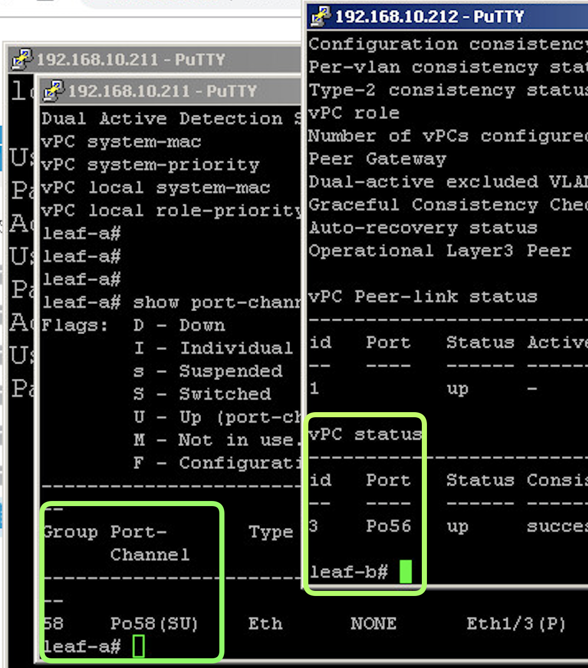
show vpc status show the Peer Link Connectivt and ALso list the Port Channels that are configured on the Leafs
leaf-a# show vpc
Legend:
                (*) - local vPC is down, forwarding via vPC peer-link

vPC domain id                     : 100
Peer status                       : peer adjacency formed ok
vPC keep-alive status             : Disabled
Configuration consistency status  : success
Per-vlan consistency status       : success
Type-2 consistency status         : success
vPC role                          : primary
Number of vPCs configured         : 1
Peer Gateway                      : Disabled
Dual-active excluded VLANs        : -
Graceful Consistency Check        : Enabled
Auto-recovery status              : Enabled (timeout = 240 seconds)
Operational Layer3 Peer           : Disabled

vPC Peer-link status
---------------------------------------------------------------------
id   Port   Status Active vlans
--   ----   ------ --------------------------------------------------
1           up     -

vPC status
----------------------------------------------------------------------
id   Port   Status Consistency Reason                     Active vlans
--   ----   ------ ----------- ------                     ------------
343  Po5    up     success     success
leaf-a# show vpc role

vPC Role status
----------------------------------------------------
vPC role                        : primary
Dual Active Detection Status    : 0
vPC system-mac                  : 00:23:04:ee:be:64
vPC system-priority             : 32667
vPC local system-mac            : 70:7d:b9:f3:f1:c5
vPC local role-priority         : 101
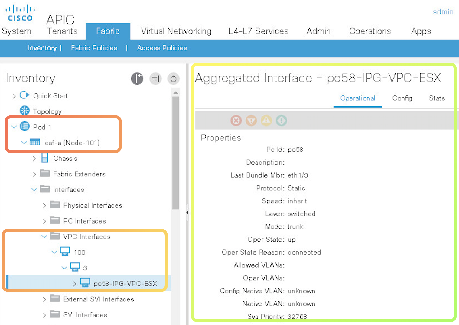
Notice that in the above configuration the Port Channel Number is NOT the same , one 56 and other is 58 for the SAME port channel configured towards a single end host
Note once the vPC config above is complete you can verify your config in the UI
Lab 3. Configure Cisco ACI Logical Constructs
High Level Steps
- Create a Tenant
Sales- skip the step to create the VRF. - Create a VRF named
Pre-SalesunderSalestenant - Without creatign aBridge Domainin the same step. Each tenant can have one or more VRFs, or share one default VRF with other tenants when there is no overlapping IP addressing being used in the ACI fabric. - Create a bridge domain, named
Presales-BD, associated with the Presales VRF inside theSalestenant.
A bridge domain is a unique Layer 2 forwarding domain that contains one or more subnets. Each bridge domain must be linked to a VRF. By default, unicast routing is enabled. ARP flooding is disabled so that unicast routing will be performed on the target IP address. Endpoint dataplane learning controls whether the remote leaf switch should update the IP-to-VTEP information with the source VTEP of traffic coming from this bridge domain.
Note: First-hop security and other policies are enabled on a per tenant bridge domain basis. As the bridge domain may be deployed on a single or across multiple leaf switches, the first-hop security threat control and mitigation mechanisms cater to a single switch and multiple switch scenarios. 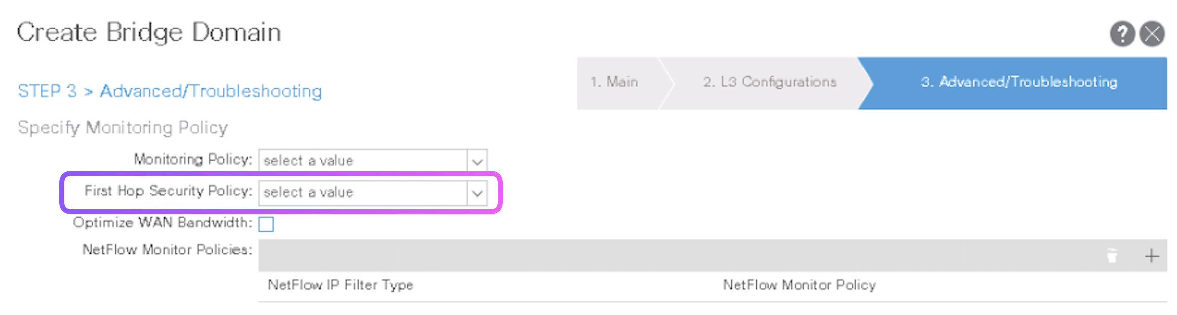
- Configure four subnets for the Presales-BD with these default gateways:
10.0.1.254/24,10.0.2.254/24,10.0.3.254/24,and10.0.4.254/24.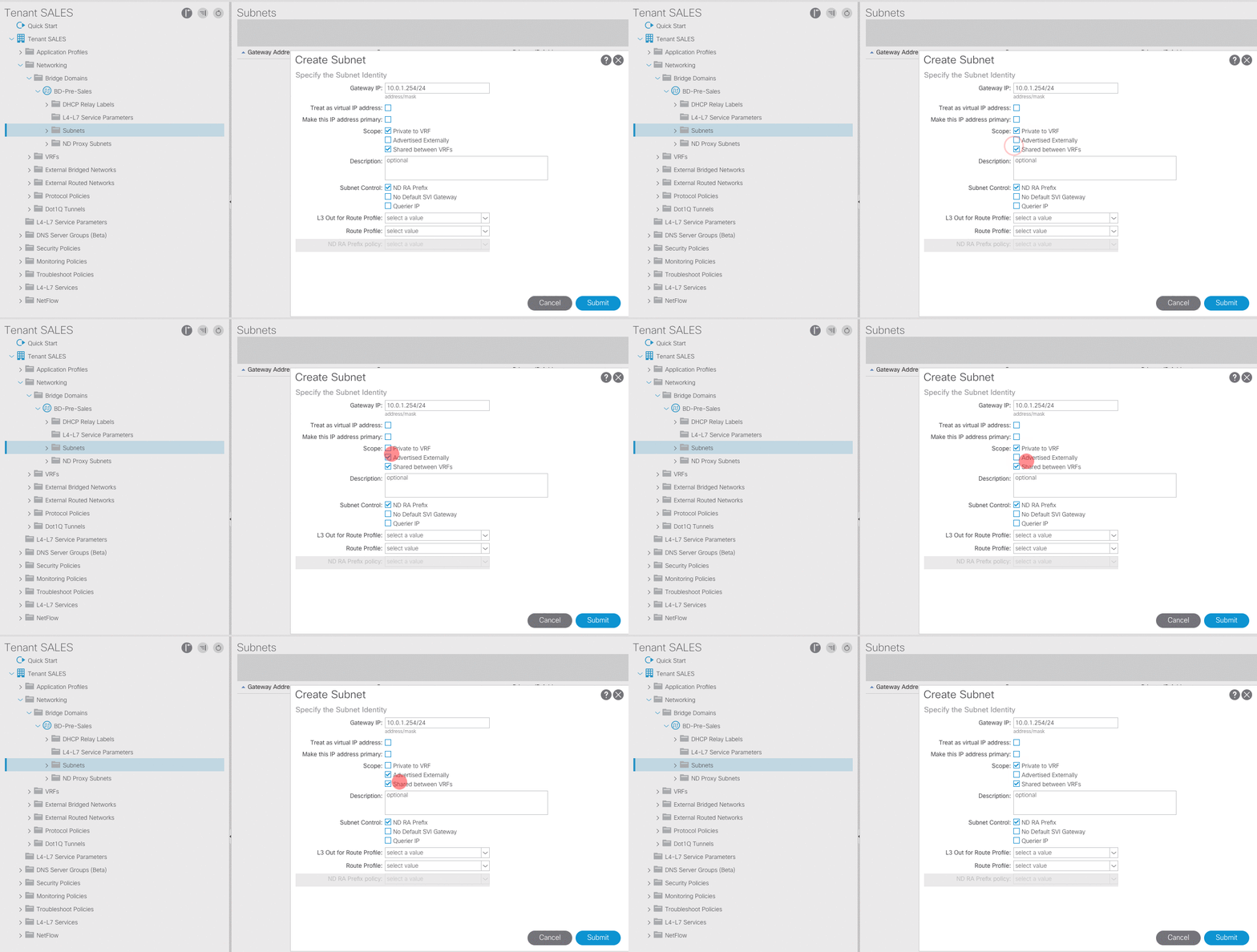
-
Create Application Profile
Tiered-Appand create EPGsWeb,App,DB - Create another filter named
HTTPaddHTTPunder it. -
Configre a filter names
Basic-Ping-SSHand under it createICMP,SSH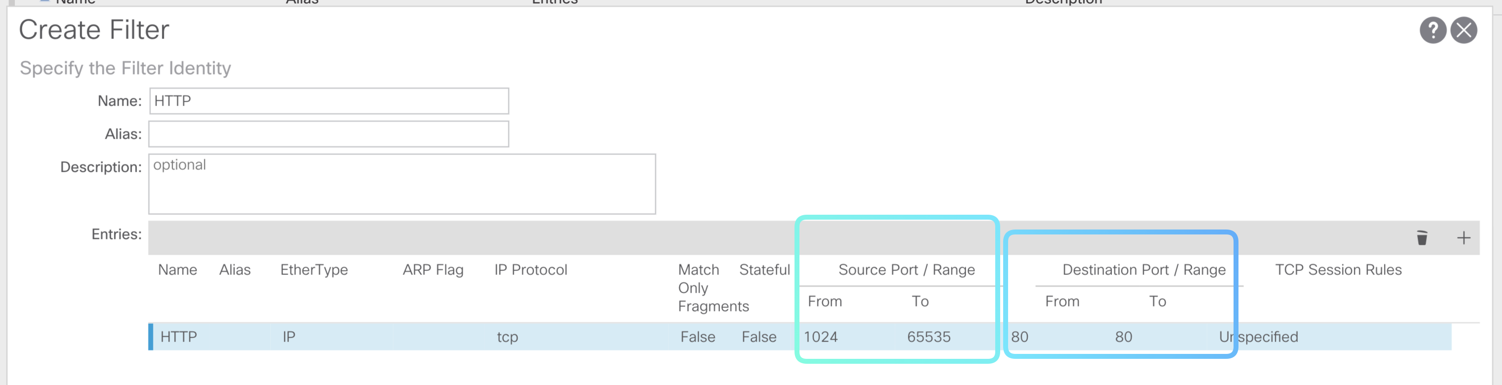
- Create a Contract
Web-Accessand include the filterBasic-Ping-SSHandHTTP
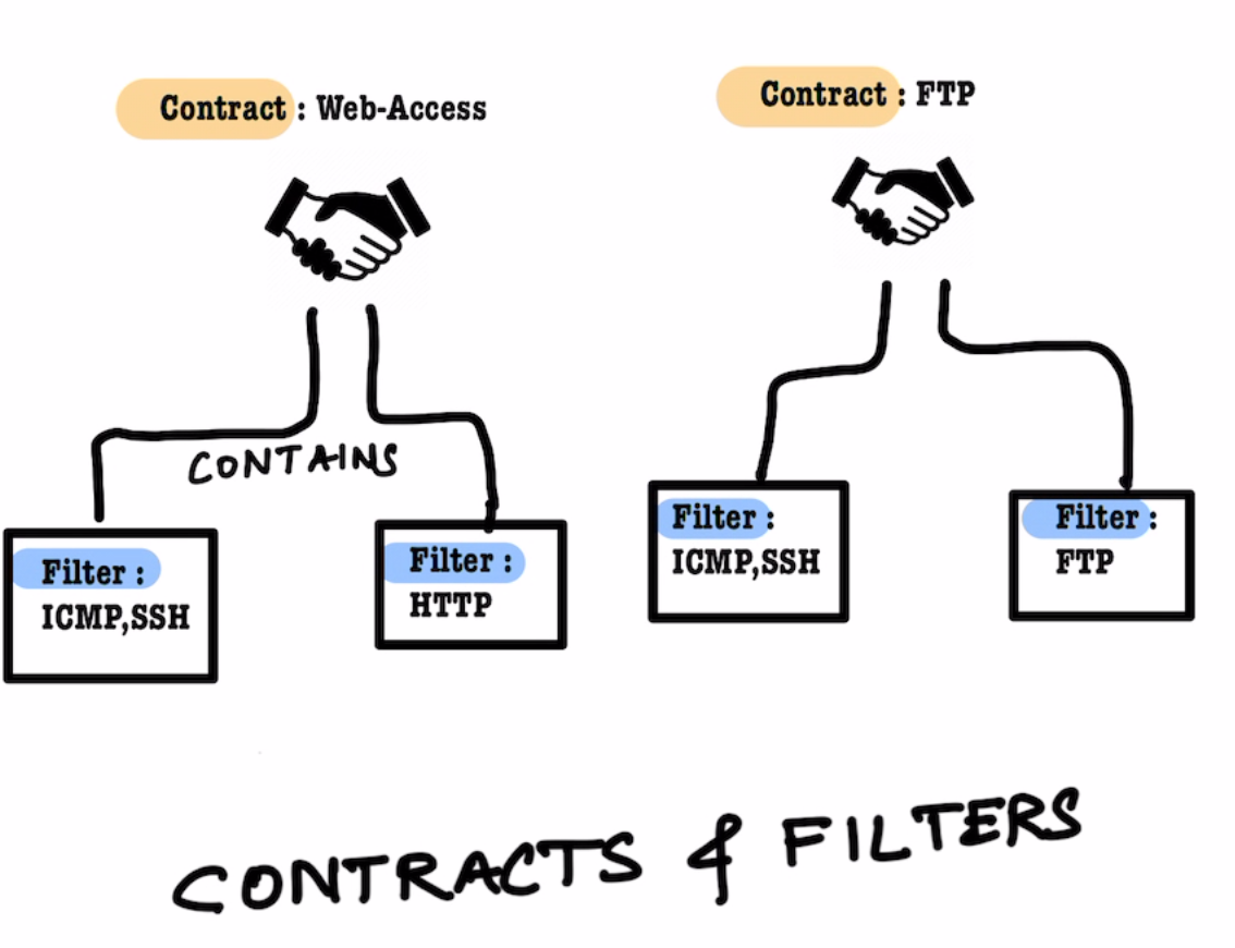
- Finally do the following
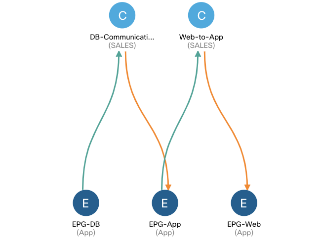
Lab 4. Configure VMM Domain Integration
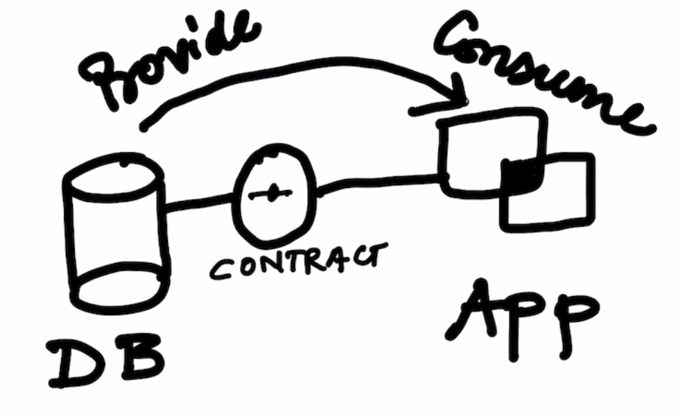
PICTURE DRAWING HERE
Cisco ACI supports three integration methods with VMware vCenter:
-
Distributed Virtual Switch (DVS)
-
Cisco Application Virtual Switch (Cisco AVS)
-
Cisco ACI Virtual Edge (AVE)
- Create a
vCenter VMM Domainin ACI and also configure the Dynamic VLAN Range .
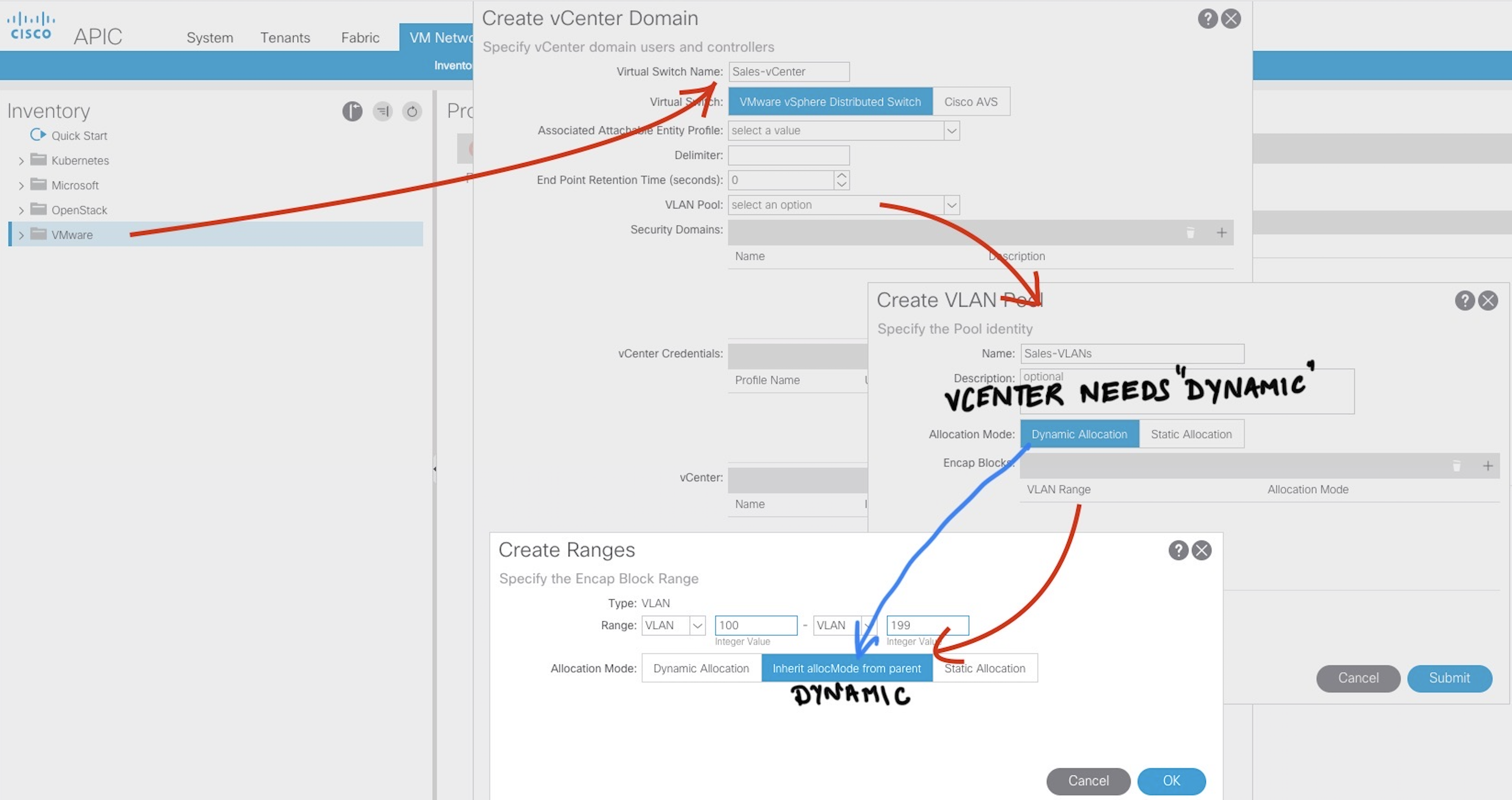
- Provide the vCenter Credentials and IP Address of vCenter
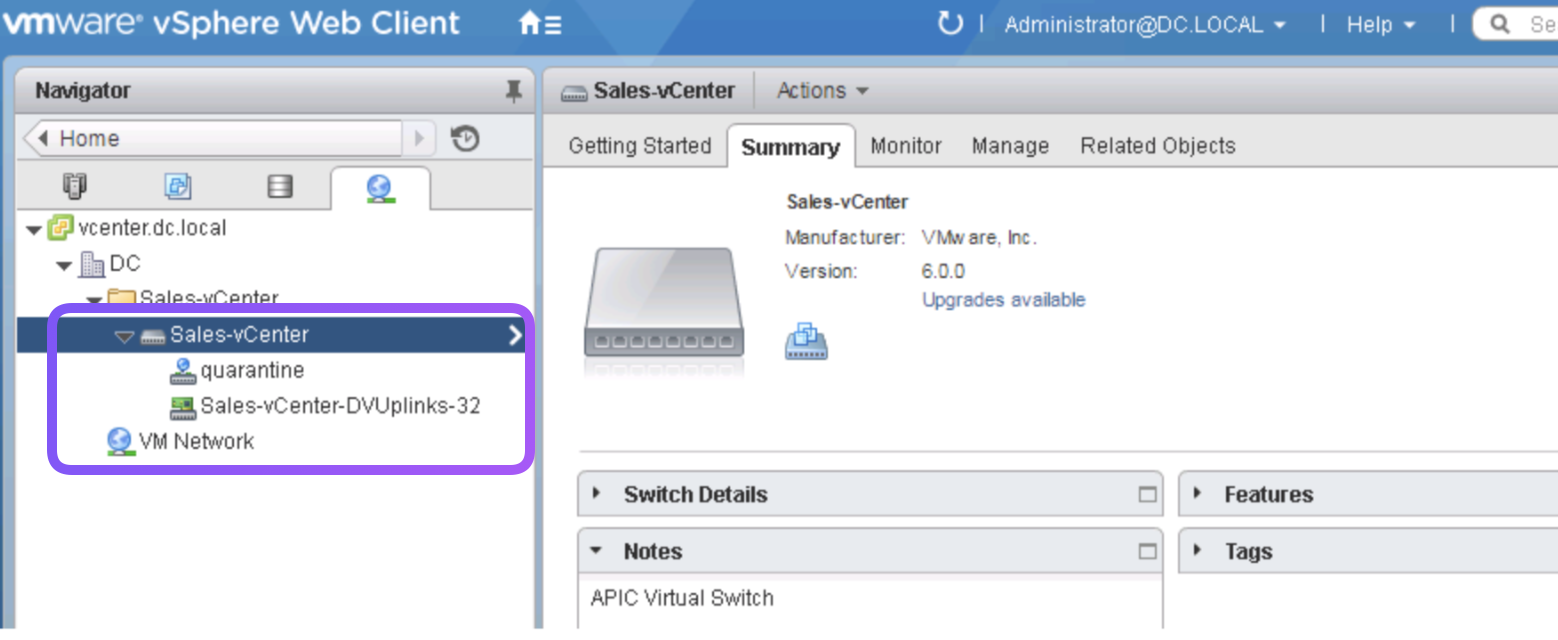
- The steps provisions VMWare DVS named
Sales-vCetnerin the VMWare environment
-
Create an
AAEPnamevCenter AAEPand join thevCenter VMM Domainand theESXPolicy Group created inLab 2 -
Now go to the
Interface Policy GroupESXand attach thevCetner AAEPto it as well. -
Add ESXi Host 192.168.10.62 to the DVS Switchs and assign the uplinks
For this lab

vmnic2 --- uplink1
vmnic3 --- uplink2
-
Ensure CDP is on in vCetner side
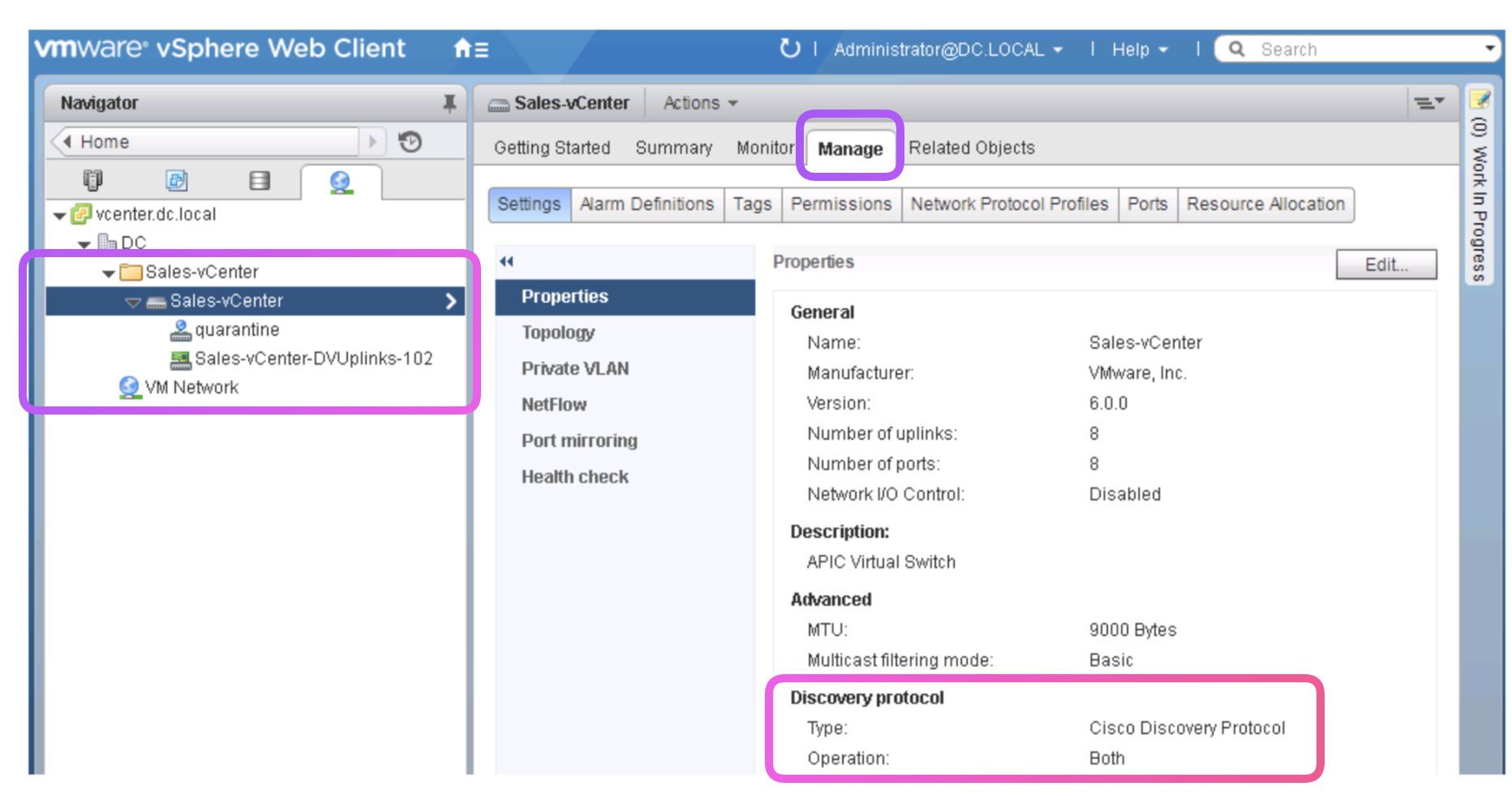
-
Verify the Leaf is discovered
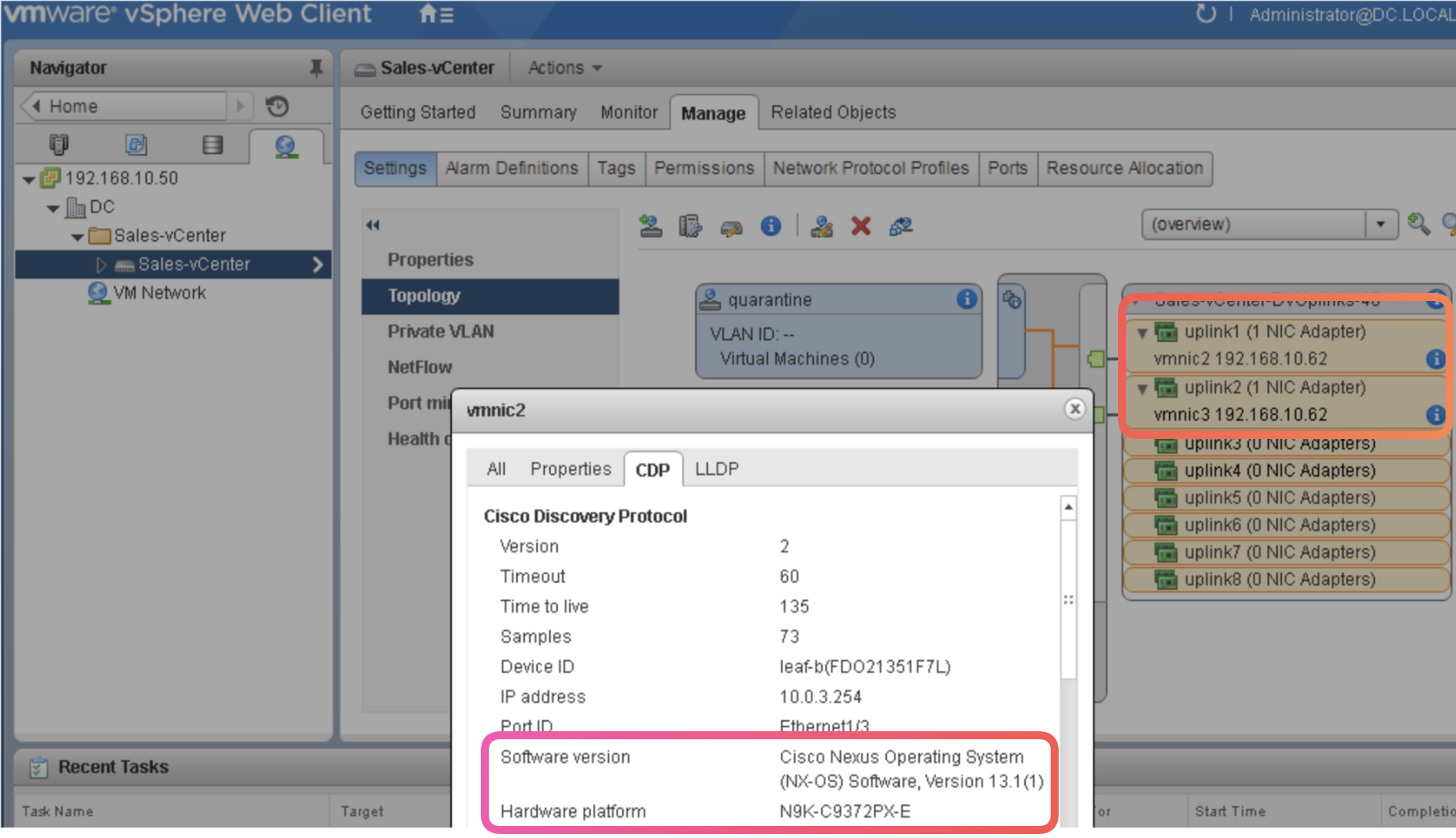
-
Now go the APIC and look for the Uplink
vmnicsthere ans see the discovered peers (leafs)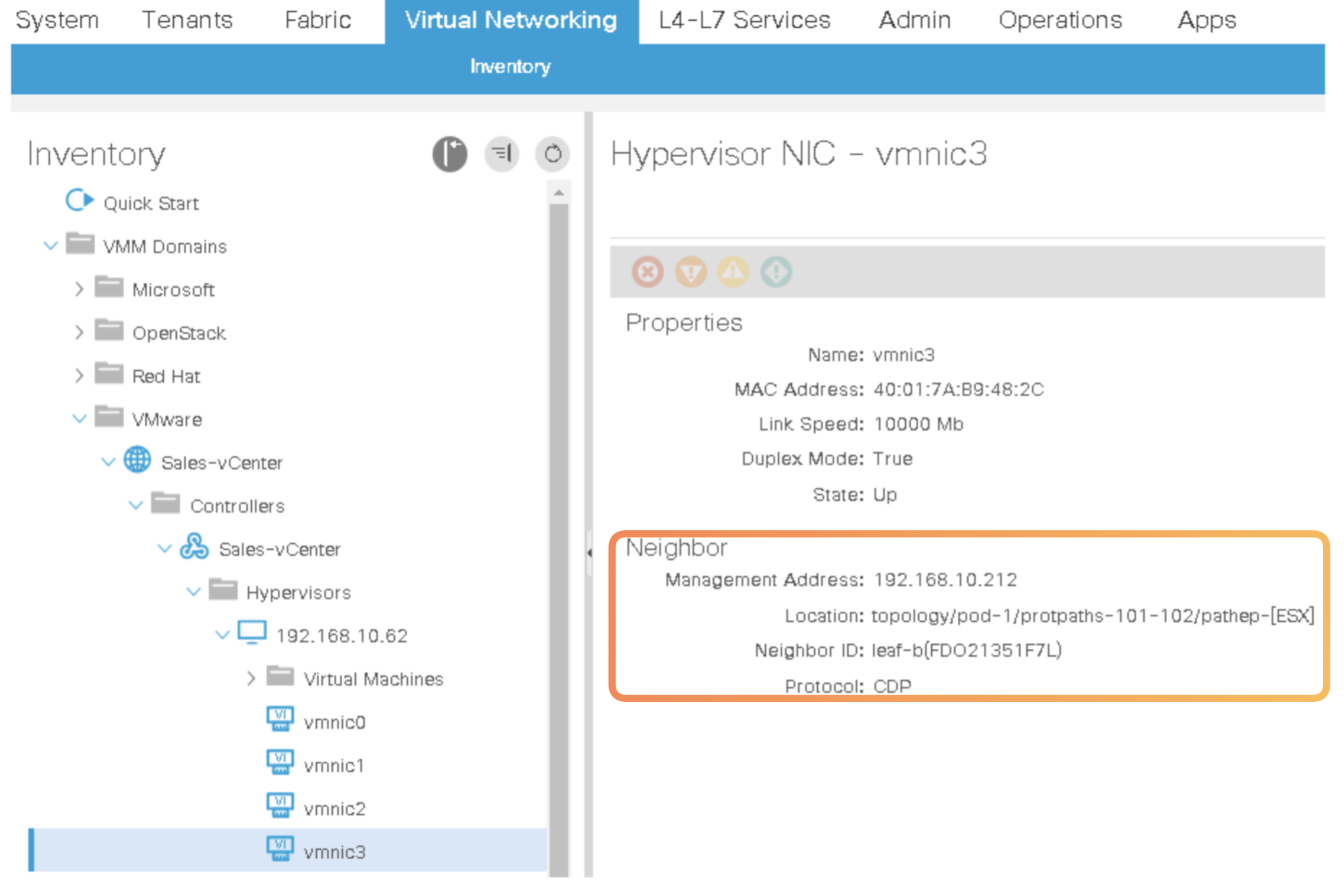
-
Now associate the
Application ProfilesDomain (VMs and BareMetals)to the VMM Domain created.
This will create the EPGs under this Application Profile as port groups in VMWare! 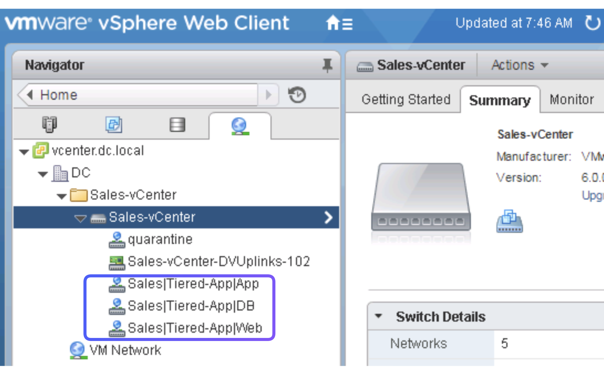
Now these Port Groups can be assigned to different VMs which in ACI map to different EPGs.
Lab 5. Deploy Cisco ACI Virtual Edge and Microsegmentation
Lab 6. Integrate Cisco ASAv with Cisco APIC
Cisco Application-Centric Infrastructure (ACI) provides the capability to insert Layer 4 through Layer 7 functions using an approach that is called a service graph. It can be considered as a superset of service insertion. Meaningful Layer 4 through Layer 7 services can include firewalls, load balancing, SSL offloading, and application acceleration.
In this activity you will deploy ASAv as a service in the Cisco ACI. The traffic between the DB and BACKUP EPGs will go through the ASAv. You will implement two types of operations:
- managed and
- unmanaged mode
and identify the differences between the two.
High Level Steps
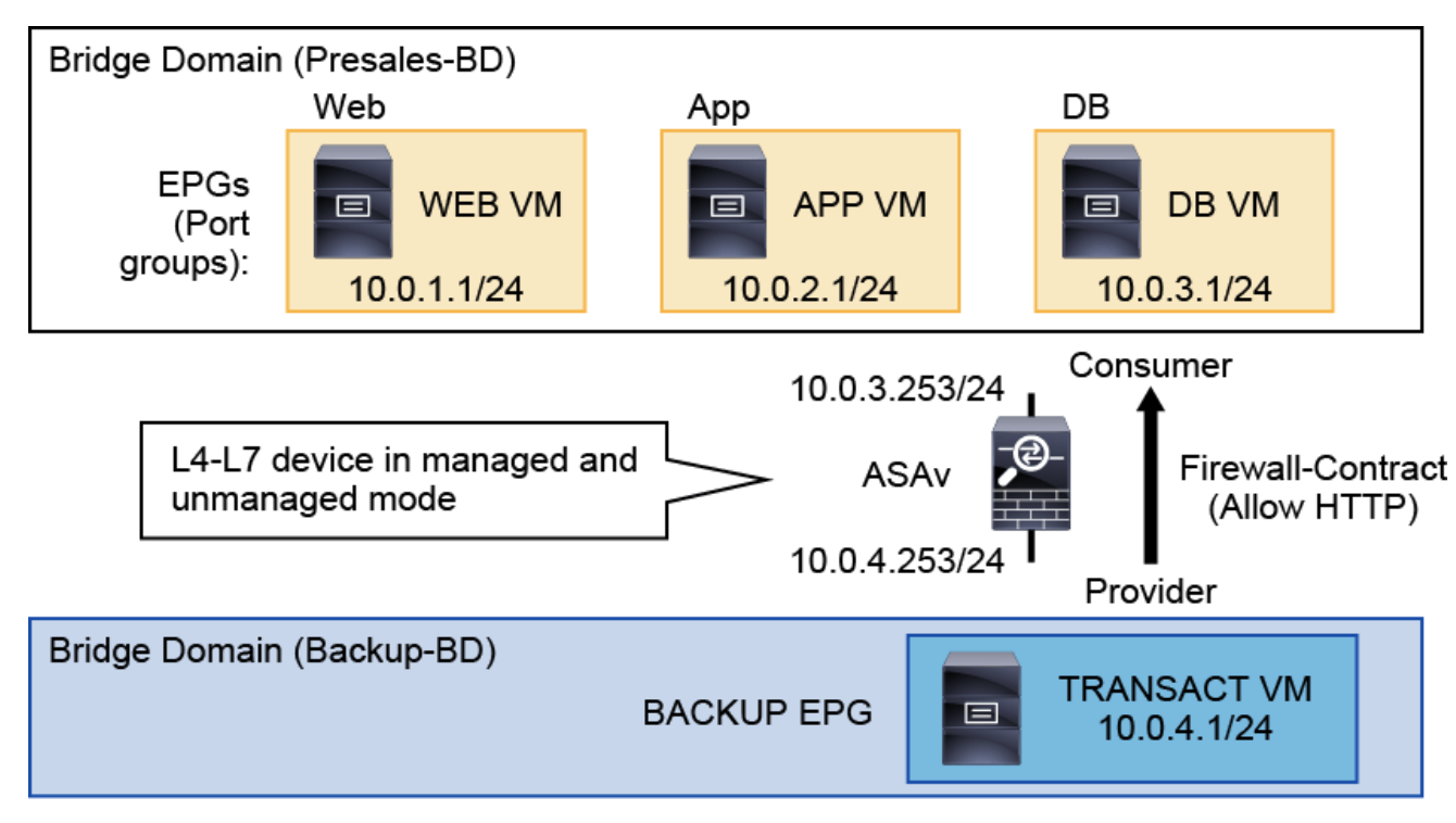
-
Step 1. LOAD the device package A device package contains the mappings and abstrations of the object model of the device that is being controlled and the scripts to configure the device.
L4–L7 Services > Packages > Quick Start > Import Device Package(asa-device-pkg-1.3.10.24.zip)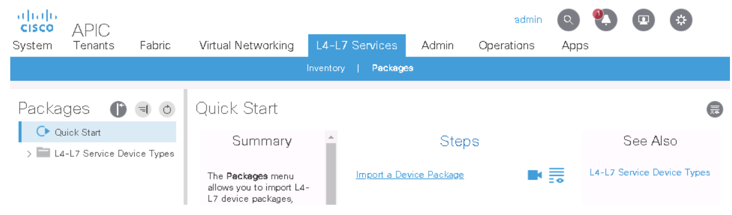
-
Step 2. REVIEW the details of the package You should see several web policy profiles, for routed and transparent mode. All of them initially permit web traffic, with different combinations of IP version and NAT.
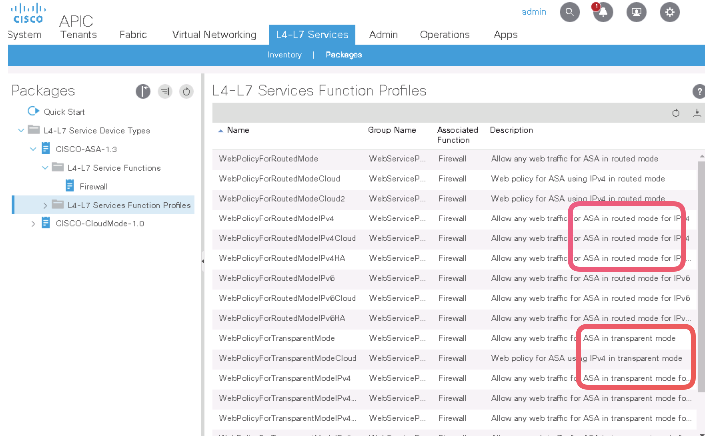
EXAMINE WebPolicyForRoutedMode, the first profile in the list. This section is the configuration placeholder for a Cisco ASA deployment in the Layer 3 mode. Among others, you will see the configuration of an ACL and the external and internal interfaces.
NOTE: If you do not customize these settings, the firewall will be configured with a single ACL (access-list-inbound) to permit HTTP and HTTPS.
- Step 3. Create TENANT Networking
- Create
Backup-BDwith thePresalesVRF** - Create a new EPG (
Backup), associate it with the new bridge domain (Backup-BD) and check the optionAssociate to VM Domain ProfilesAND Associate it with yourVMM domain (Sales-vCenter)
- Create
-
Step 4. Reuse the TRANSACT VM as a BACKUP VM Delete the
10.0.4.254/24subnet from thePresales-BDbridge domain and configure it for theBackup-BDbridge domain. assign theTRANSACT VMto theBackup port group. -
Step 6. Verify OOB Management to ASAv All communication between the Cisco APIC and the Cisco ASAv occurs via HTTPS. The Cisco ASAv has been pre-provisioned with the necessary commands to enable HTTPS/SSH management access.
-
Step 7. Notice all the ports of the ASAv in VSphere are assigned to the default
VM Network. Once L4-L7 is complete you will see the ports change. -
Step 8. Login to ASAv and verify basic configs AND HTTPs access
interface Management0/0 nameif management security-level 100 ip address 192.168.10.71 255.255.255.0 route management 0.0.0.0 0.0.0.0 192.168.10.254 1 aaa authentication http console LOCAL aaa authentication ssh console LOCAL aaa authentication enable console LOCAL aaa authorization exec LOCAL auto-enable http server enable http 0.0.0.0 0.0.0.0 management ssh 0.0.0.0 0.0.0.0 management username admin password CsI1KX6iq7UBl3KK privilege 15 -- Important -
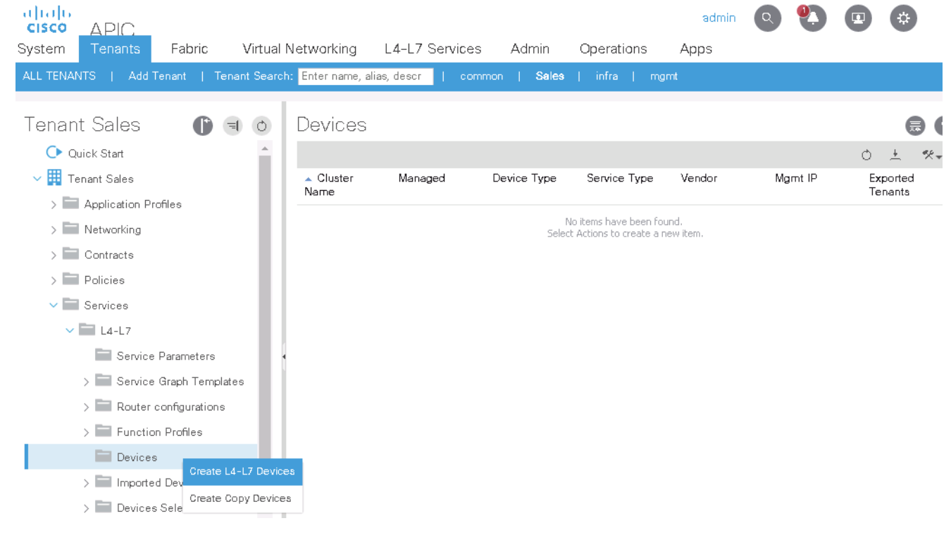
Step 9. Create a L4–L7 Device for Cisco ASAv
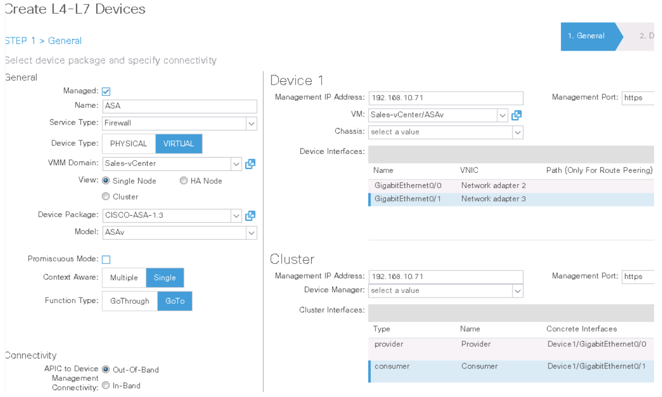
-
Step 10. Create and Apply Service Graph
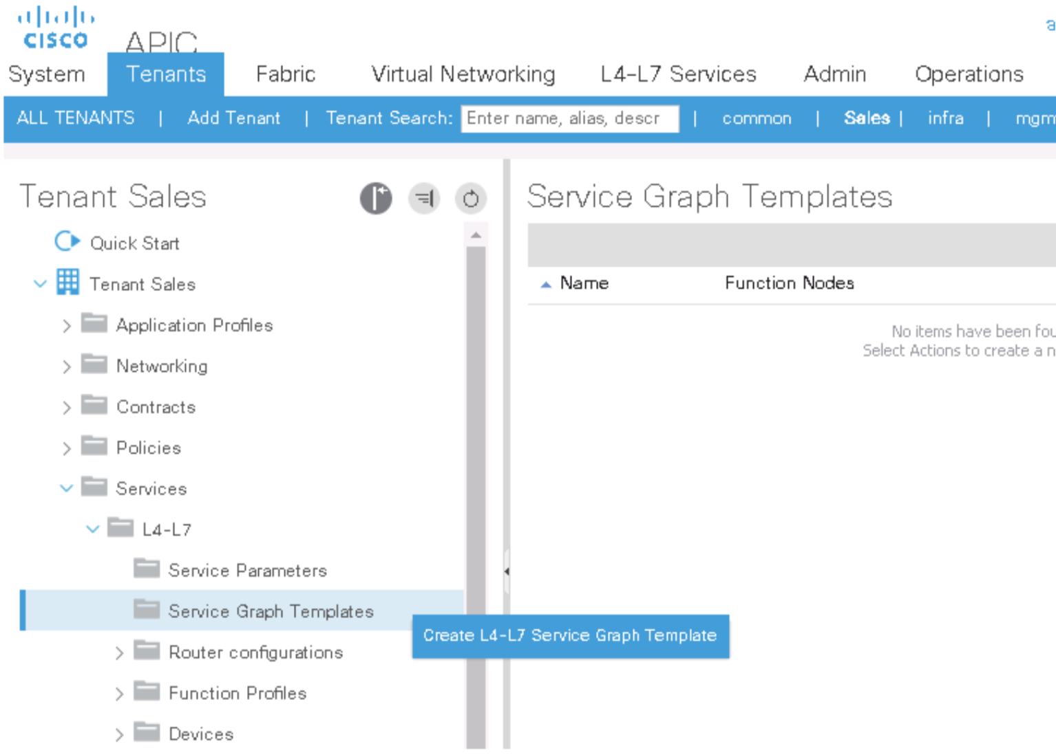
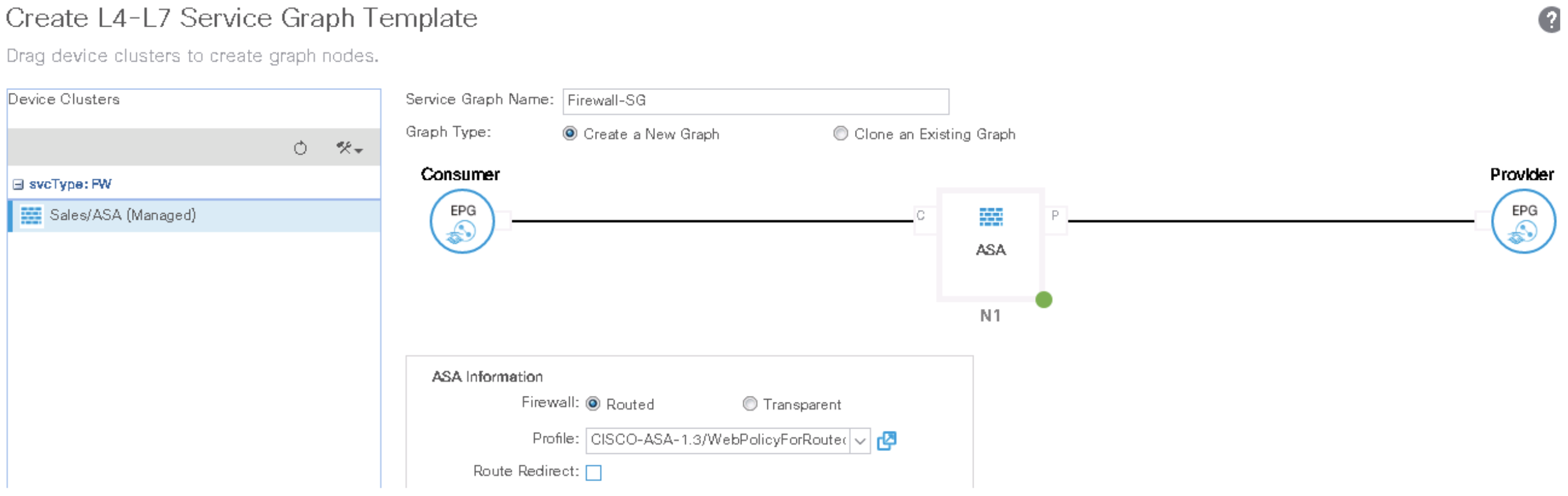
Check the Above Config Here
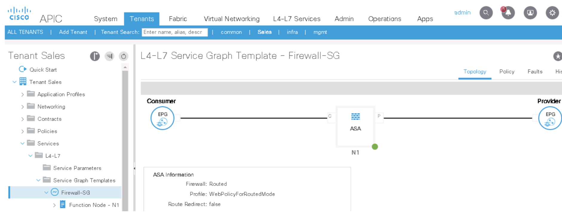
NOTICE That nothing has yet been deployed on the ASAv
-
Step 9. Apply the service graph template to the DB-to-Backup traffic
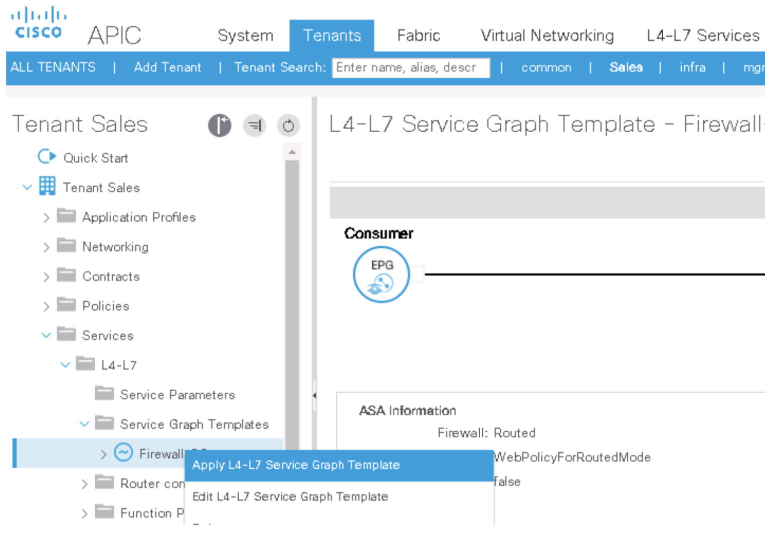
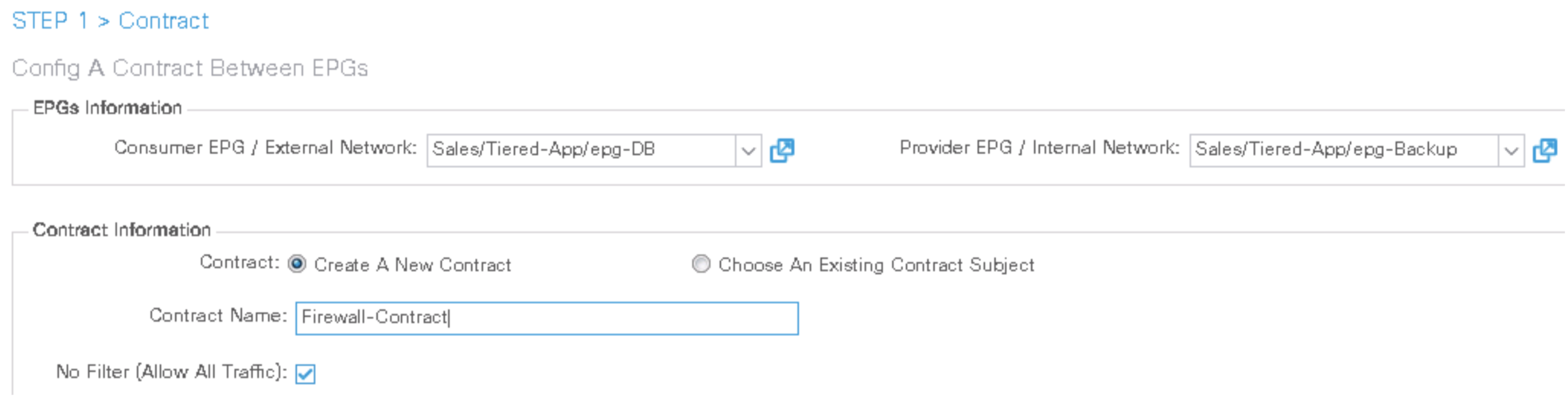
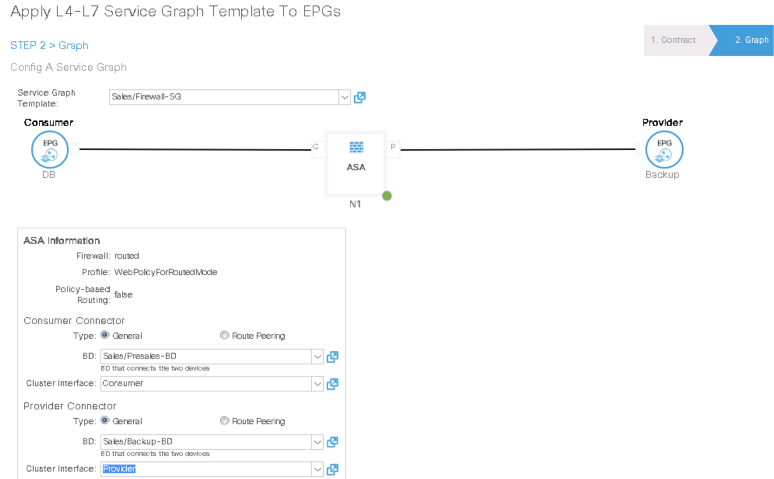
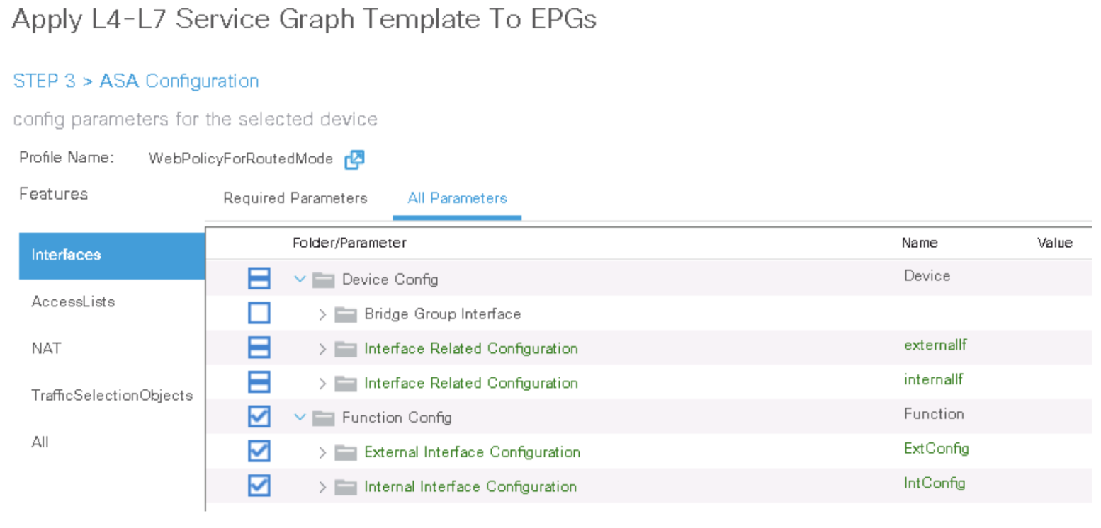
Double-click the network_ip_address field of the network object web_server and enter the IP address of the TRANSACT VM (10.0.4.1/32).

-
Step 9. Check ASA Config
ciscoasa# show running-config access-list access-list access-list-inbound extended permit tcp any object web_server eq www access-list access-list-inbound extended permit tcp any object web_server eq https ciscoasa# show running-config access-group access-group access-list-inbound in interface externalIf ciscoasa# show running-config object network object network web_server subnet 10.0.4.1 255.255.255.255 ciscoasa# show running-config interface GigabitEthernet 0/0 ! interface GigabitEthernet0/0 nameif internalIf security-level 100 no ip address ciscoasa# show running-config interface GigabitEthernet 0/1 ! interface GigabitEthernet0/1 nameif externalIf security-level 50 no ip address -
Step 9. Verify Contract is applied
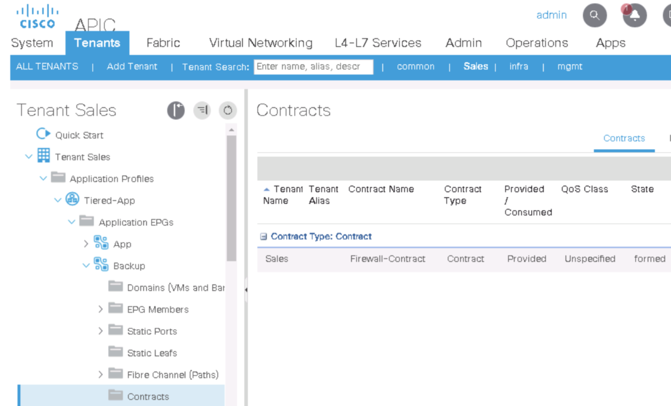
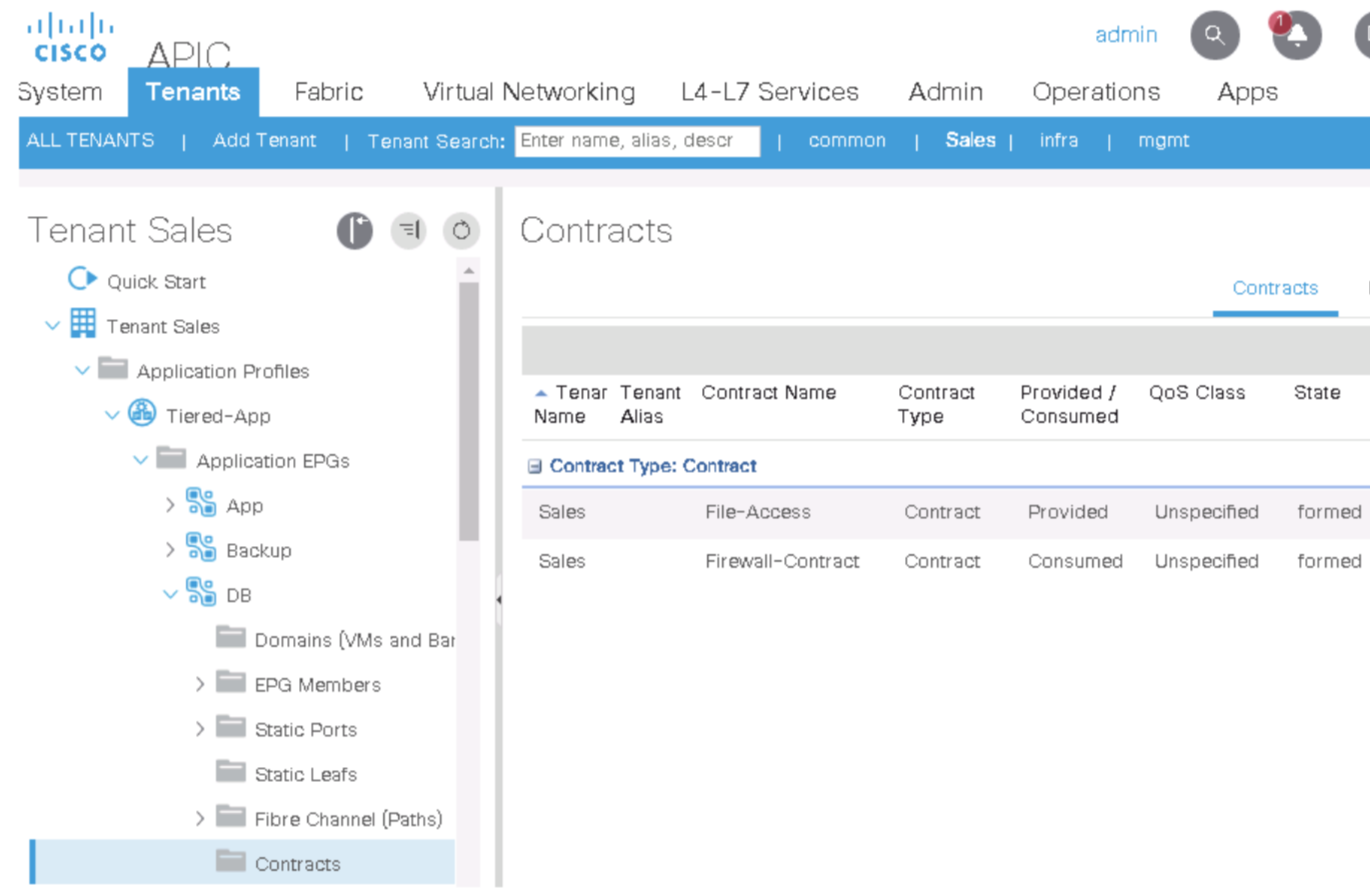
Also lok at the Subject
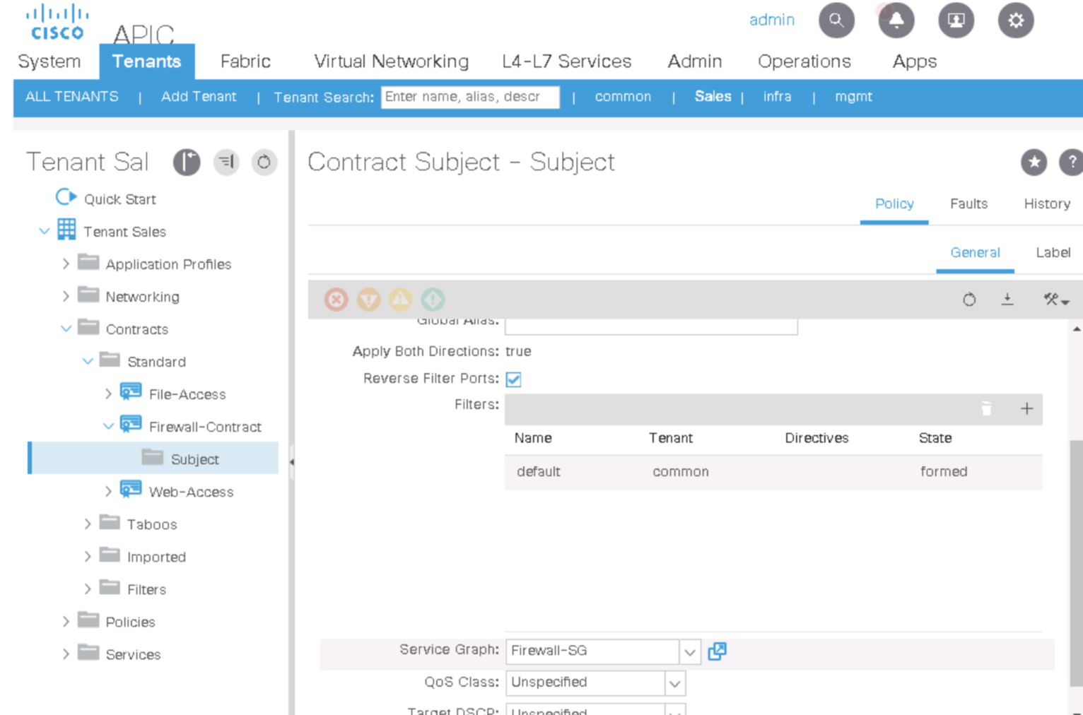
-
Step 9. Look at the Topology
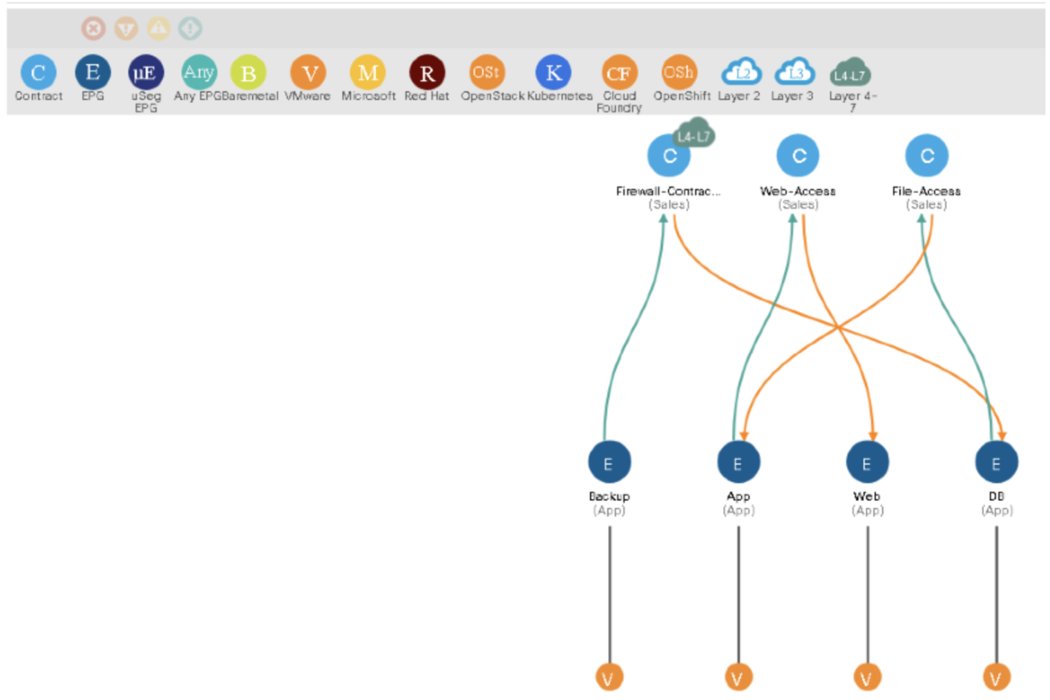
-
Step 9. Examine the L4–L7 service parameters of the provider EPG (Backup).
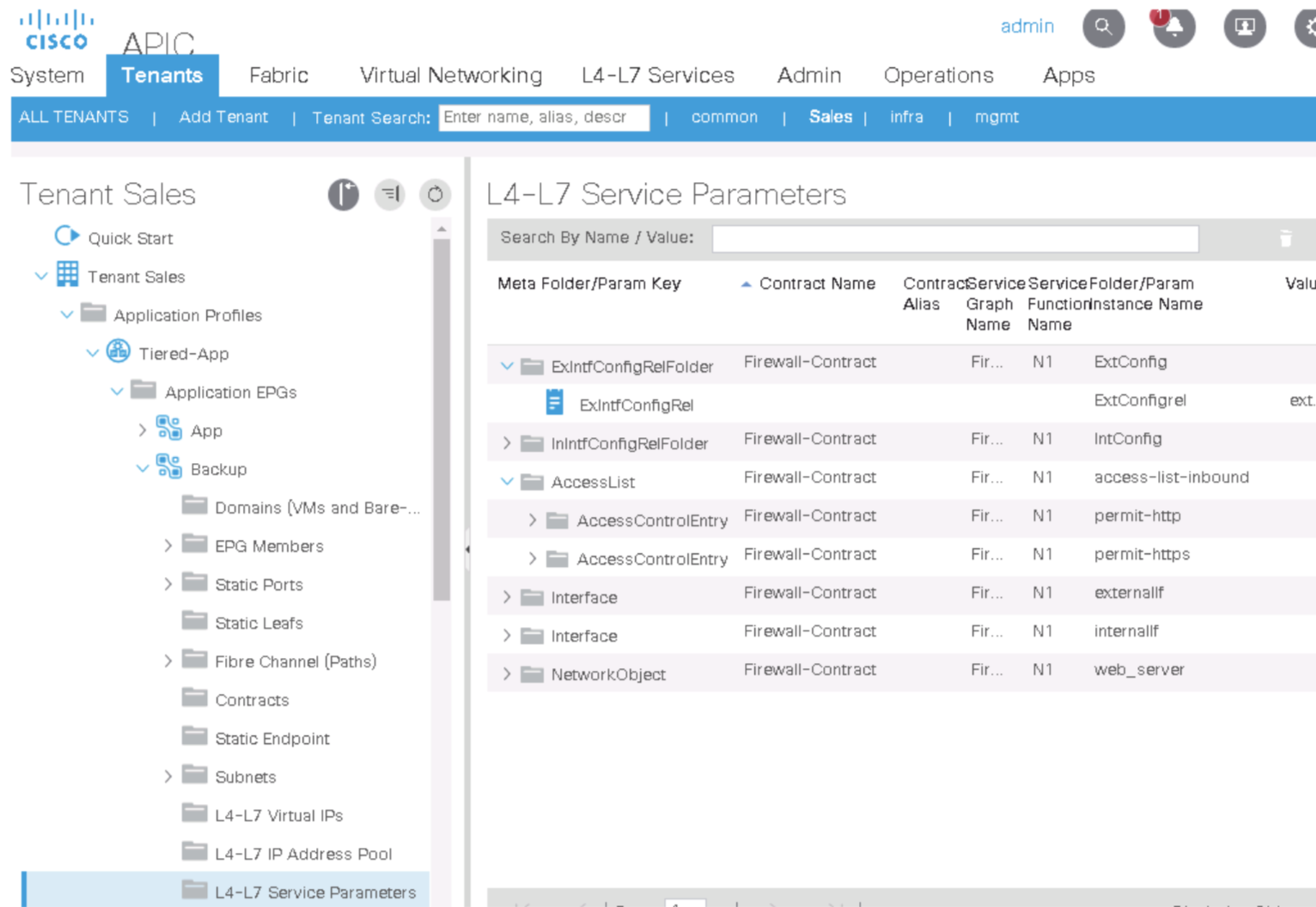
-
Step 10. Examine the deployed graph instance and device.
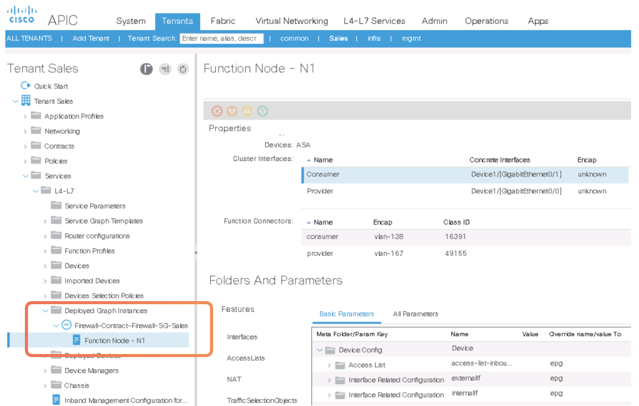
-
Step 9. Go to Services > L4–L7, expand Deployed Devices, and examine the ASA-Presales device. You should see the VLAN encapsulations for the cluster devices.
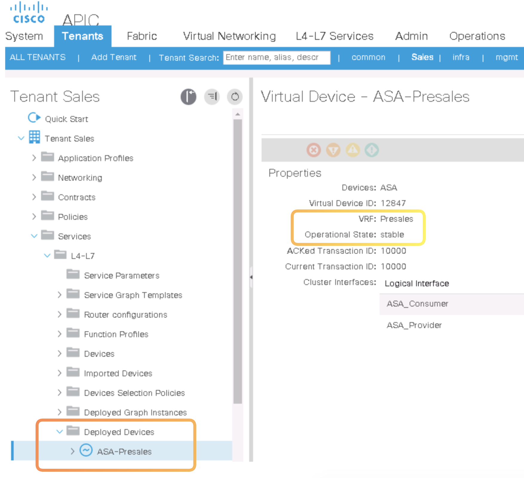
-
Step 9. Notice the VM Settings
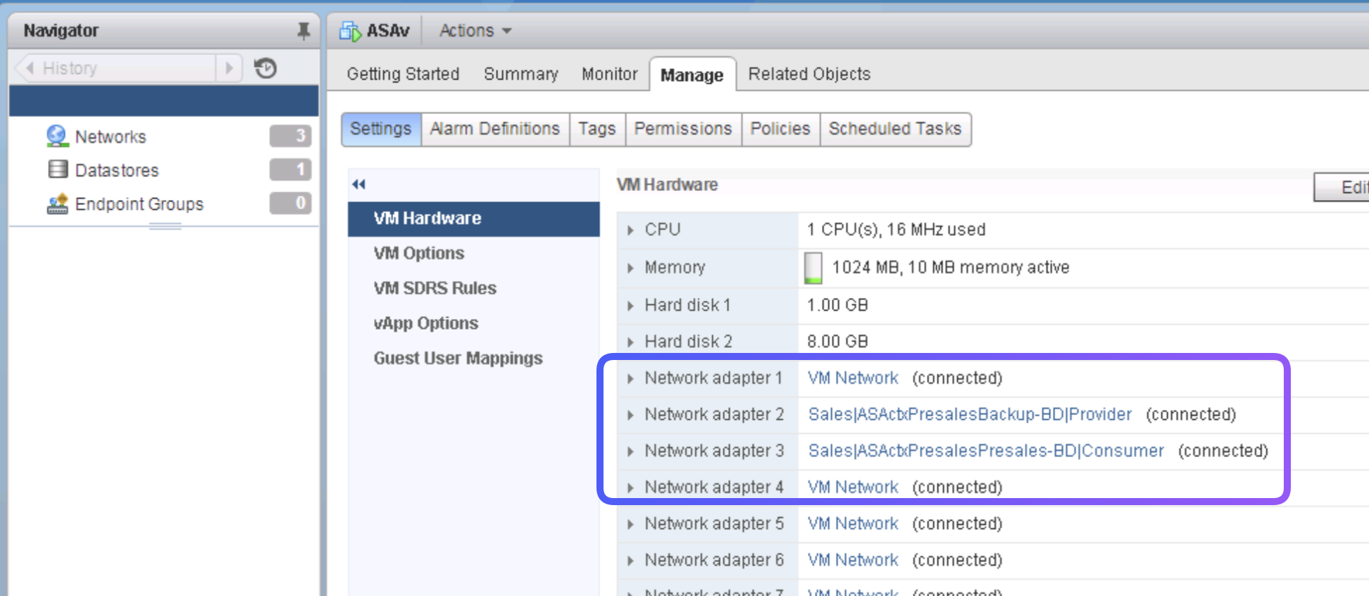
-
Step 9. Notice the Roll Back Options
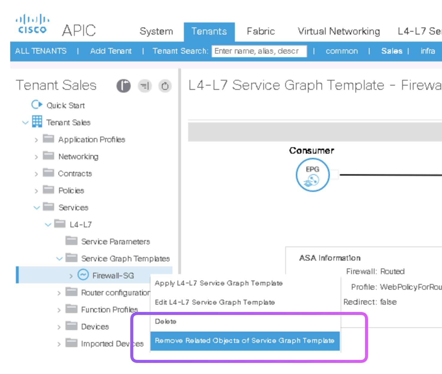
-
Step 9. Customize the Cisco ASAv Configuration You can assign ASAv interface IP Addresses right from the ACI.
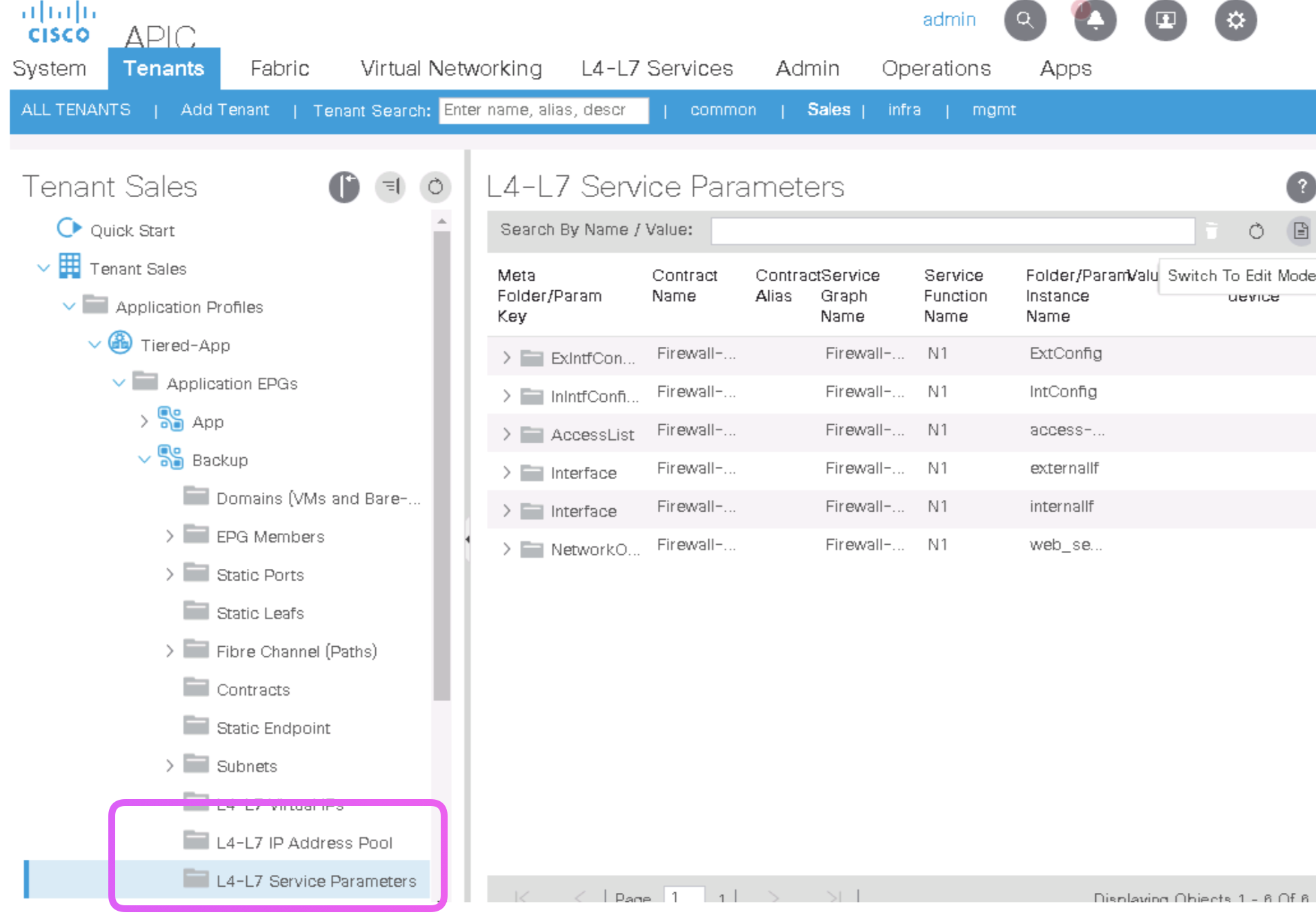
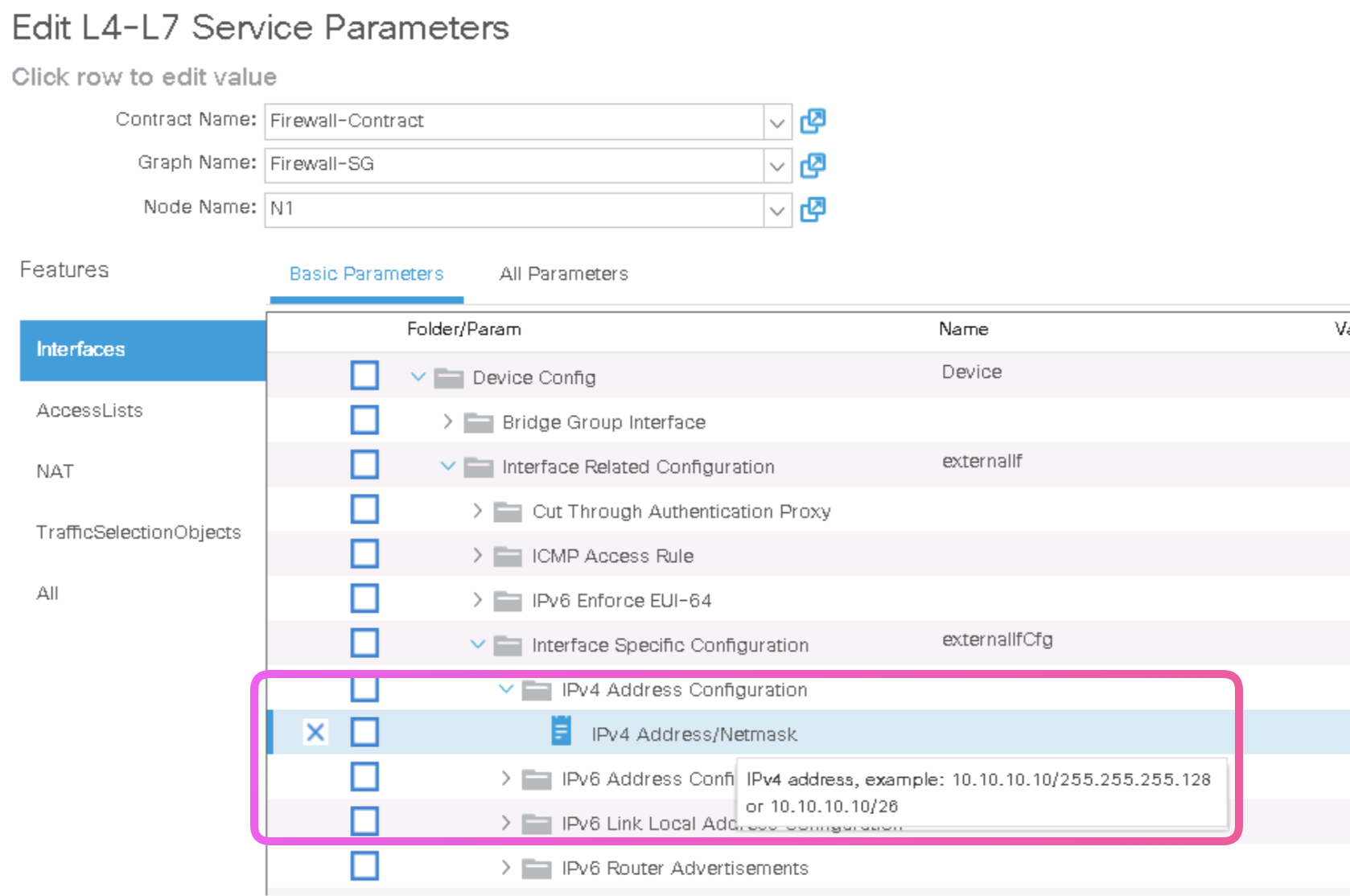
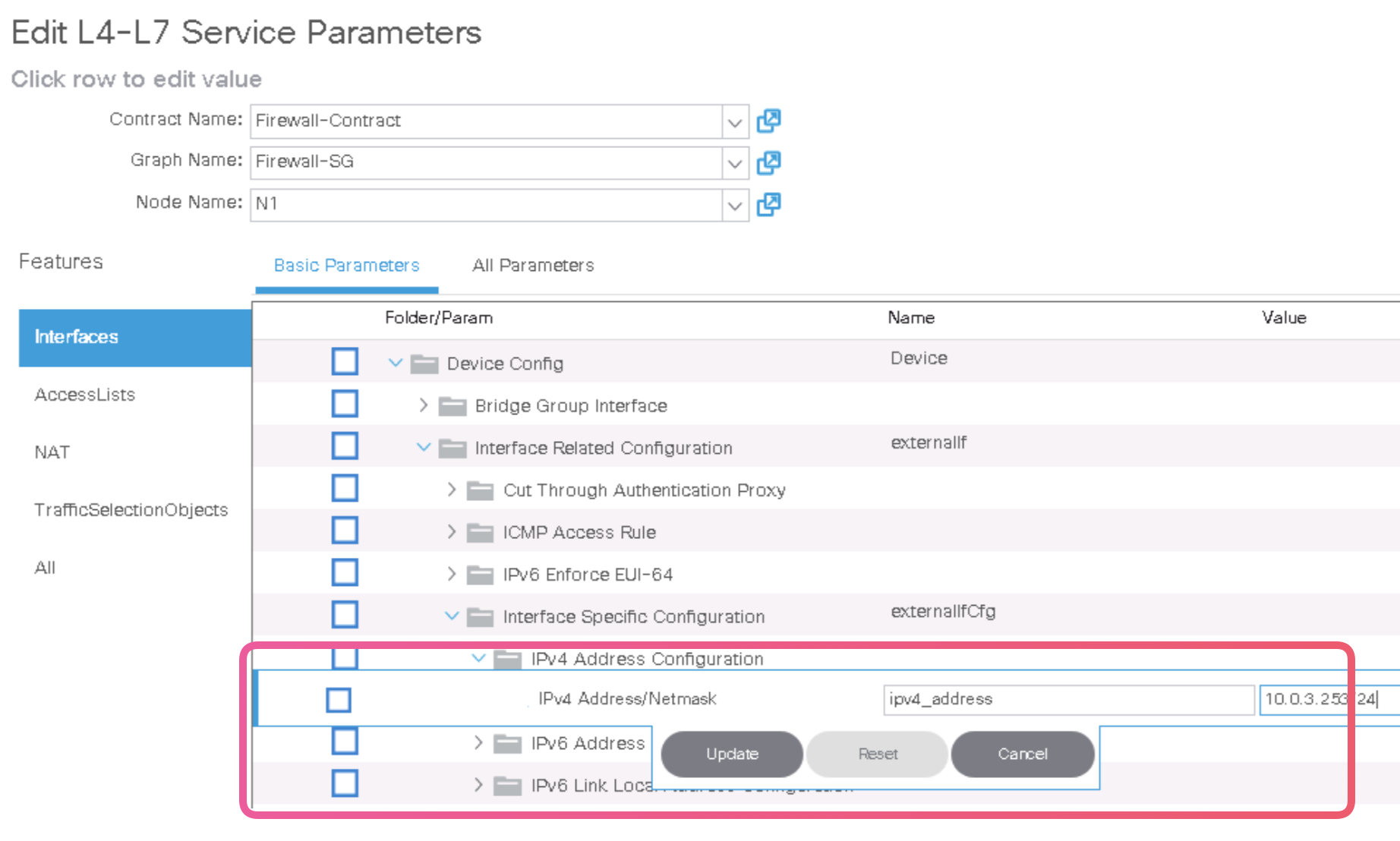
ciscoasa# show interface ip brief
Interface                  IP-Address      OK? Method Status                Protocol
GigabitEthernet0/0         10.0.4.253      YES manual up                    up
GigabitEthernet0/1         10.0.3.253      YES manual up
You can verify the connectivity in the ASA
  ciscoasa# show access-list
  access-list cached ACL log flows: total 0, denied 0 (deny-flow-max 4096)
              alert-interval 300
  access-list access-list-inbound; 2 elements; name hash: 0xcb5bd6c7
  access-list access-list-inbound line 1 extended permit tcp any object web_server eq www (hitcnt=3) 0x1560fdca
    access-list access-list-inbound line 1 extended permit tcp any host 10.0.4.1 eq www (hitcnt=3) 0x1560fdca
  access-list access-list-inbound line 2 extended permit tcp any object web_server eq https (hitcnt=0) 0x122c48e4
    access-list access-list-inbound line 2 extended permit tcp any host 10.0.4.1 eq https (hitcnt=0) 0x122c48e4
Use L4–L7 Device in Unmanaged Mode
-
Step 1. Exami
-
Step 2. Exami
-
Step 3. Exami
-
Step 4. Exami
-
Step 5. Exami
-
Step 6. Exami
ACI Operations and Troubleshooting (CI-ACIOPS)
Outline: ACI Operations and Troubleshooting (ACIOPS)
Course Introduction
Overview
Course Goal and Objectives
Prerequisites
Course Outline
Module 1: Cisco ACI Component Review
Lesson 1: Cisco ACI Architecture and Network Review
ACI and APIC Review
Tenant, Management Tenant and Context Review
VLAN and VRF Review
Bridge Domain Review
Application Profile Review
End Point Group Review
Lesson 2: Cisco ACI Policy Review
ACI Contract Review
ACI Filter Review
ACI Subject Review
Lesson 3: Cisco ACI Unified Fabric Review
Cisco ACI Server Connectivity Review
Cisco ACI Network Connectivity Review
Cisco ACI Switch Review
Cisco ACI Routing Review
Lesson 4: Cisco ACI External Connectivity Review
Layer 2 External Switching Review
Layer 3 External Routing Protocol Review
Lesson 5: Customer Setup Review
Scaling Cisco ACI
Migration Paths to Cisco ACI
Module 1 Lab Exercises
Lab 0 – Lab Topology and Access
Lab 1 - Reviewing the Cisco ACI Environment
Lab 2 – Tenant and Context
Lab 3 - VLAN and VRFs
Lab 4 – Bridge Domains
Lab 5 – Application Profiles
Lab 6 - End Point Groups
Lab 7 – External Bridged Networks
Lab 8 – External Routed Networks
Lab 9 – Physical and VMM Domains
Module 2: Cisco ACI Operations
Lesson 1: The Cisco ACI Control Plane and Packet Flow
Determine ACI Packet Flow
Single DB/Single EPG with Two Endpoints on the Same Leaf
Single BD/Single EPG with Two Endpoints on Different Leafs
Single BD/Two EPGs with One Endpoint in EPG on the Same Leaf
Two BDs/Two EPGs with One Endpoint in Each EPG on the Same Leaf (Routed Packet)
Lesson 2: Cisco ACI Router Baseline
Route Profiles Overview
Configurating a Route-Profile
Applying a ‘Default’ Route-Profile
Applying a Route-Profile at the Bridge Domain
Applying a Route-Profile at the Bridge Domain Subnet
Applying a Route-Profile at the External EPG and External EPG Subnet
Applying a Route-Profile at the L3out as an Interleak Policy
Lesson 3: Configure and Verify Changes in the Network
Configure and Verify Interface Profiles
Configure and Verify Static EPGs
Verify Interfaces and Encapsulation
Lesson 4: Cisco ACI Logging and DHCP Relay
Logging data and data retention
Activity and audit logs
DHCP Relay service
Infra/Tenant
L3 Out
L2 Out
Module 2 Lab Exercises
Lab 10 – ACI Packet Flows
Lab 11 - Verify Routing Information
Module 3: Cisco ACI Troubleshooting
Lesson 1: Cisco ACI Troubleshooting Tools
Atomic Counters and Network Time Protocol
Cisco ACI Endpoint Tracker Application
End to End Testing
Endpoint to Endpoint Testing
Endpoint Group to Endpoint Group Testing
Discovering Paths and Testing Connectivity with Traceroute
Lesson 2: On-Demand Diagnostics and Statistics
Gathering On-Demand Collection and Statistics
Cisco Switched Port Analyzer (SPAN)
Access SPAN (or infrastructure SPAN)
Fabric SPAN
Tenant SPAN
ACI Monitoring and Diagnostics
Fabric Troubleshooting Diagnostics
Lesson 3: Cisco Nexus Data Broker Integration with ACI
The Cisco Nexus Data Broker
Test Access Points (TAPs)
Configure SPAN Sessions
Synchronize SPAN Sessions
Data Broker Use Case
Lesson 4: Cisco ACI Troubleshooting Methodology and Scenarios
Techsupport Files
Atomic Counters
Faults and Health Scores
Troubleshooting Scenarios
Troubleshoot Fabric Initialization
Troubleshoot APIC High Availability and Clustering
Troubleshoot Firmware and Image Management
Troubleshoot Rest Interface
Troubleshoot Management Tenant
Troubleshoot Common Network Services
Troubleshoot Unicast Data Plane Forwarding and Reachability
Troubleshoot Policies and Contracts
Troubleshoot Bridged Connectivity to External Networks
Troubleshoot Routed Connectivity to External Networks
Troubleshoot Virtual Machine Manager Insertion
Troubleshoot Layer 4 Through 7 Services Insertion
Troubleshoot ACI Fabric Node Process Crash Troubleshooting
Troubleshoot an APIC Process Crash
Troubleshoot Spanning Tree Loops
Module 3 Lab Exercises
Lab 12 – ACI Monitoring Tool
Lab 13 – Using Statistics
Lab 14 – Configure Syslog Monitoring
Lab 15 – Configure ERSPAN
Lab 16 – Create and Test an EPG-to-EPG Atomic Counter
Lab 17 – Using the Moquery Command
Lab 18 – Configure and Verify Contracts
Lab 19 – Examine and Enhance Fabric Access Policies
Module 4: Cisco ACI Automation
Lesson 1: The REST API
The REST API Structure
The Six Constraints of REST
REST Client–Server Constraint
REST Stateless Constraint
REST Cacheable Constraint
REST Layered Constraint
REST Code-On-Demand Constraint
REST Uniform Interface Constraint
Lesson 2: JSON and XML
JSON API Characteristics
XML API Characteristics
JSON and XML Advantages, Similarities, and Differences
Lesson 3: Cisco ACI Data Model
The Cisco ACI Programmable Network Infrastructure
The APIC Data Model
The APIC Policy Model
The Cisco ACI Object-Oriented Data Model
Module 4 Lab Exercise
Lab 21 – Configure the APIC Using the REST API
Module 5: Cisco ACI Backups, Snapshots, Rollbacks and Upgrades
Lesson 1: Cisco ACI Backups, Snapshots and Rollbacks
Backing up Configurations
Snapshots
Rollbacks
Lesson 2: Cisco ACI Upgrades
Firmware Repository
Software Image
Switch Image
Catalog Image
Module 5 Lab Exercises
Lab 22 - Backups and Snapshots
Lab 23 - Create and Use Configuration Backups
Appendix (Optional Labs)
Lab 23 – Explore Spanning Tree Protocol and Loop Prevention
Lab 24 – APIC Cluster Operations and Troubleshooting
Lab 25 – Nexus Spine and Leaf Switch Operations
Lab 26 – Upgrade APIC and Switch Firmware
Implementing Cisco Application Centric Infrastructure – Advanced
https://www.cisco.com/c/dam/en_us/training-events/le31/le46/cln/marketing/exam-topics/600-660-DCACIA.pdf
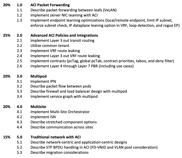
- Learning notes from BRKACI-3545 Ciscolive Session
- Read
https://www.cisco.com/c/en/us/solutions/collateral/data-center-virtualization/application-centric-infrastructure/white-paper-c11-739989.htmlEMEAR DCV PVT - ACI troubleshooting with TAC experts - LiveLessons Course
- INE Course
-
Look at the Youtube Video : VXLAN Part 6 - BGP EVPN Configuration on Nexus 9000 - Look at the videos here : https://www.youtube.com/watch?v=EHoAtPaW3oo
Learn VLXLAN which lays the foundations right


Reference Videos
BRKACI-2008 - A Technical Introduction into ACI
BRKACI-2004 - How to setup an ACI fabric from scratch
BRKACI-2102 - ACI Troubleshooting
BRKACI-2003 - Deployment Options for Interconnecting Multiple ACI Fabrics
BRKACI-3503 - Extending ACI to Multiple Sites - Dual Site Deployment Deep Dive
BRKACI-2020 - Understanding Cisco ACI Architecture and Scalable Layer-3 DCI / WAN integration with OPFLEX
BRKACI-2001 - Integration and Interoperation of Existing Nexus Networks into an ACI Architecture
BRKACI-2121 - Making the best of Services Automation with ACI Service Graph and Python
BRKSEC-3004 - Deep Dive on Cisco Security in ACI
Basic Packet Flow in an ACI
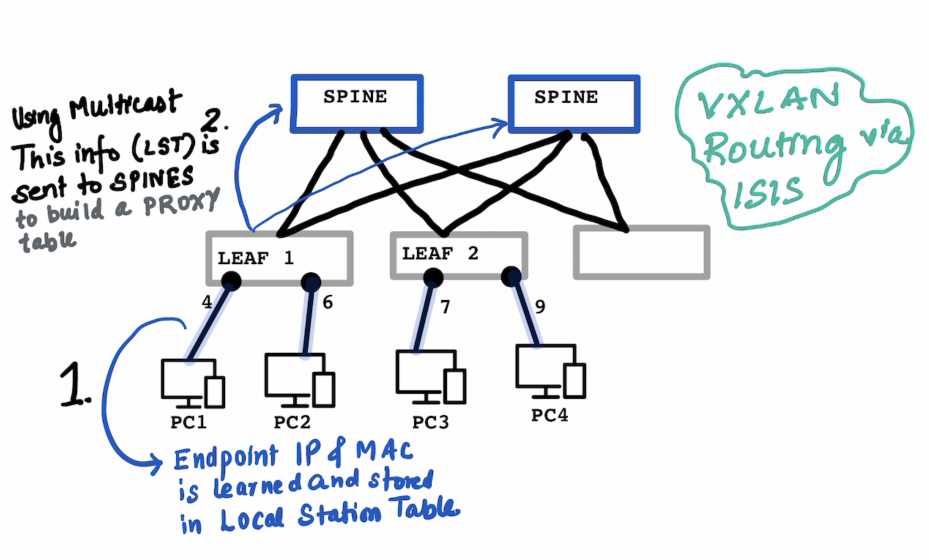
Local Station Table and Global Station Table are on Leaf Proxy Table is on the Spine
ON THE LEAF : In the local station table the IP address , MAC Address and port number is learned on the Leaf
The learning switch does not know the subnet mask of the learned the IP Address. (hence /32)
In a “normal” switch the “switching” happends based on the learnt MAC Address , in ACI it is a combination if Switching and Routing.
# Local Station LEAF-1

IP Address   MAC-Address    Port
-------------------------------------
10.1.1.1/32      MAC-PC1      Port-4
10.1.2.1/32      MAC-PC2      Port-6
# Local Station LEAF-2

IP Address   MAC-Address    Port
-------------------------------------
10.2.2.1/32      MAC-PC3      Port-7
10.1.2.6/32      MAC-PC4      Port-9
ON THE SPINE : The Leaf sends this information to the Spines using multicast , so that it can send it to multiple spines at the same time. The SPINEs build up a PROXY table which has informations on the IP Address and Corresponding VTEP.
Inter Fabric Routing setup is via ISIS Only , BGP is only used for L3 Out.
# Proxy Table for SPINE1 and SPINE2 contains everyones information

IP            VTEP1
10.1.1.1/32      192.168.1.1 (Leaf 1 VTEP)
10.1.2.1/32      192.168.1.1 (Leaf 1 VTEP)
10.2.2.1/32      192.168.1.2 (Leaf 2 VTEP)
10.1.2.6/32      192.168.1.2 (Leaf 2 VTEP)
SCENARIO 1 : When PC1:10.1.1.1 wants to talk to PC3:10.2.2.1:
ARP Process to Be Clarified and Documented later as this example is directly assuming that the IP Address is known
- A lookup is done in
Leaf1’s Local station table and is NOT found. - A look is done on the
SPINE’s proxy table , which responds back witht he VTEP address of the Leaf which has the IP Address10.2.2.1 Leaf1Stores this received information about10.2.2.1into itsGlobal Station Table- Communicatin starts on a VXLAN encapuslated packet as usual.
# Global Station Table on Leaf 1

IP            VTEP1
10.2.2.1     192.168.1.2 (Leaf 2 VTEP)
# Global Station Table on Leaf 2

IP            VTEP1
10.1.1.1     192.168.1.1 (Leaf 2 VTEP)
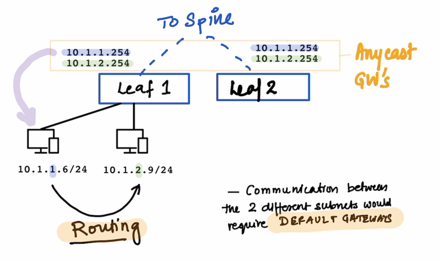
Since the two PCs above are in different Subnets , Routing would take place when they need to talk to each other.
The default gateways for the same are configured on the leafs.
10.1.1.25410.1.2.254
All these subnets are defined on the Bridge Domain Bridge Domain is your VXLAN
For communications for the devices on the same Leaf the Leaf responds to local ARP queries.
The VLANs in ACI are not significant within the ACI fabric ; The VLANs are still significant for backward compatibility with L2 Out Networks.
Endpoint
What is an endpoint ?
It’s a combination of MAC address and IP Address.
We can see it on the APIC
We can find more details about the same on the specific Leaf
MAC and /32 IP Address are stored in the Endpoint Table
Exception is L3 Out , If we use the same mechanism of learnign all the IP Address , on the MAC address on Nexus router we would have thousand of /32. Other IP Information is used int he Ip Table just as the normal routing. That is the reason why we use arp table for L3 out.
Forwarding Table Lookup Order
- First : Endpoint Table (
show endpoint) - Second : RIB (
show ip route)
End Point Group
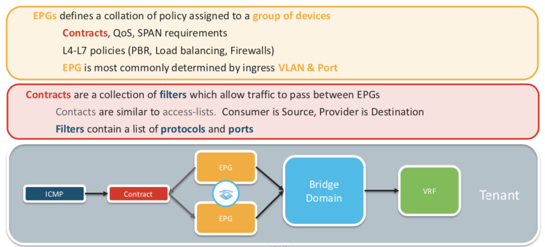
Endpoint Group is a logical grouping of hosts (EPs). Each EPG belongs to a bridge domain (BD)
EPG is used to implement the filtering with a contract.
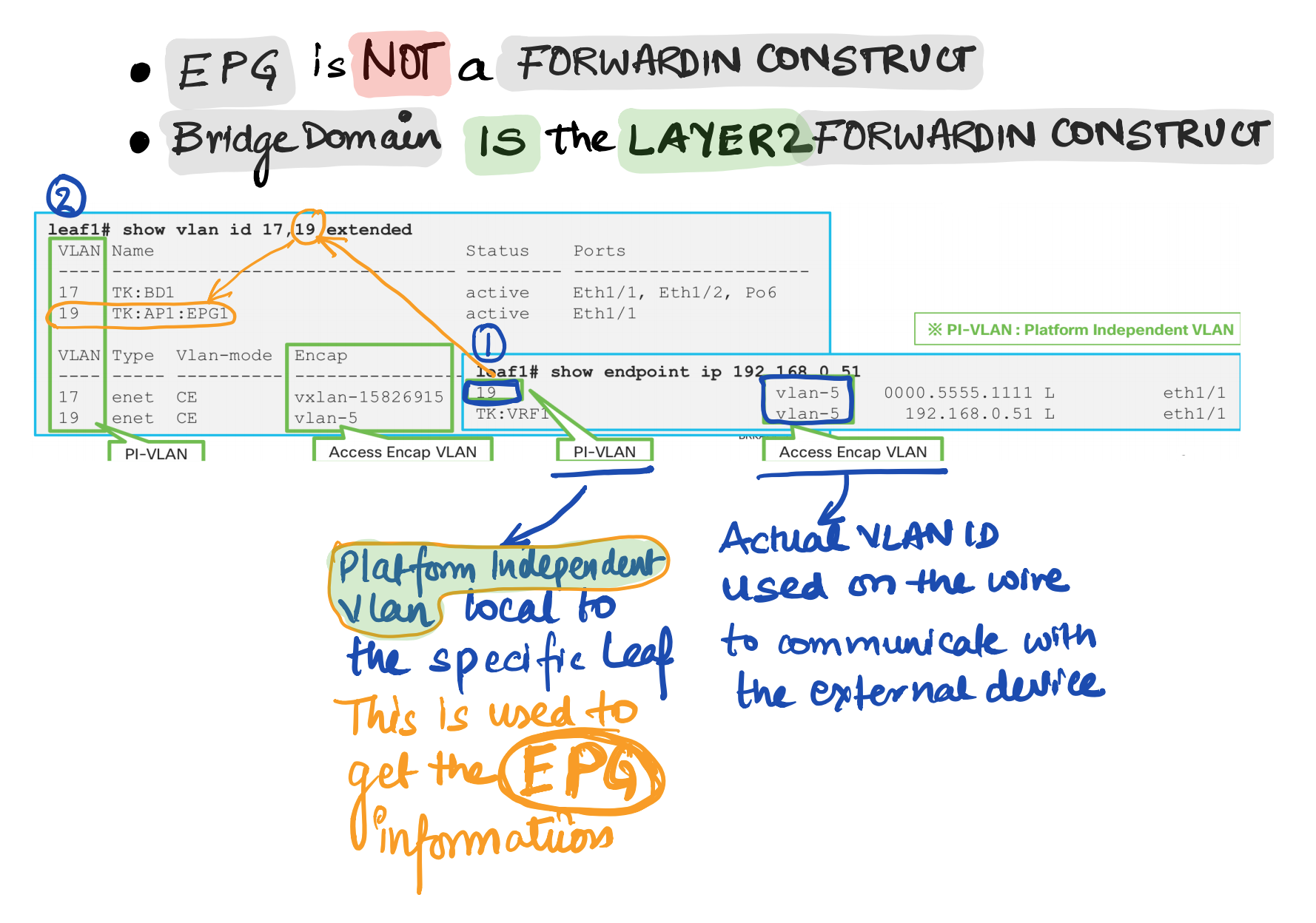
EPG is basically a security domain , but EPG is still using VLAN. So what is VLAN being used for. VLAN is just an identifier for the EPG
EPG is not a forwarding domain. Bridge Domain is the L2 Forwarding Domain If its L3 , its the VRF.
How to check endpoints
GUI
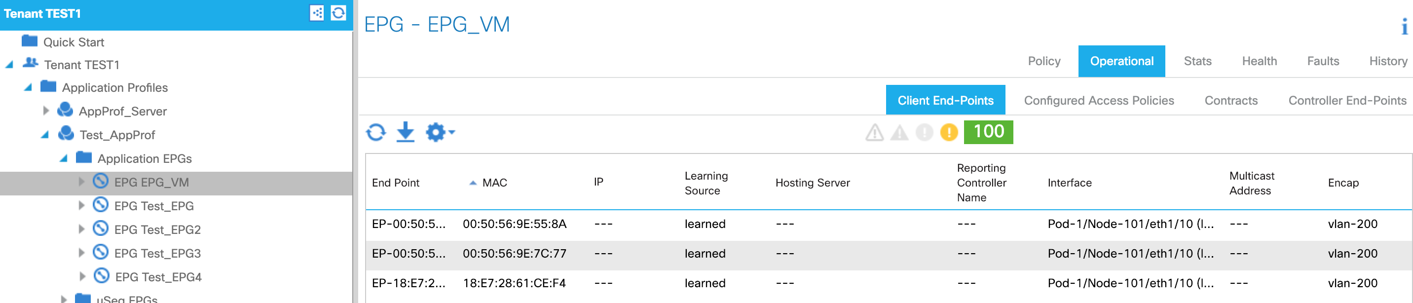
CLI
LEAF1# show endpoint ip 192.168.1.23
Legend:
 s - arp              O - peer-attached    a - local-aged       S - static
 V - vpc-attached     p - peer-aged        M - span             L - local
 B - bounce           H - vtep
+-----------------------------------+---------------+-----------------+--------------+-------------+
      VLAN/                           Encap           MAC Address       MAC Info/       Interface
      Domain                          VLAN            IP Address        IP Info
+-----------------------------------+---------------+-----------------+--------------+-------------+
16                                        vlan-3091    0050.5669.c00b L                        po19
DC1-HyperFlex-NSX:DC1-HyperFlex           vlan-3091      192.168.1.23 L                        po19


LEAF1# show vlan id 16,31 extended

 VLAN Name                             Status    Ports
 ---- -------------------------------- --------- -------------------------------
 16   DC1-HyperFlex-NSX:DC1-HyperFlex- active    Eth1/7, Eth1/21, Eth1/22,
      NSX-AP:DC1-HyperFlex-FI-ESX-               Eth1/40, Po3, Po19, Po21
      MGMT-VLAN-3091
 31   DC2-UCS-N5K-NSX:DC2-UCS-N5K-NSX- active    Eth1/21, Eth1/22, Po3
      AP:DC2-ISCSI-VLAN-1

 VLAN Type  Vlan-mode  Encap
 ---- ----- ---------- -------------------------------
 16   enet  CE         vlan-3091
 31   enet  CE         vlan-1
LEAF1#
VLAN types in ACI
Endpoint Type
PERVASIVE GATEWAY
What is pervasive GW for?
-
To be a default GW for EPs in the Fabric , All EPs can have consistent gateway IP address one hop away
-
To represent subnets (IP ranges) for a BD.
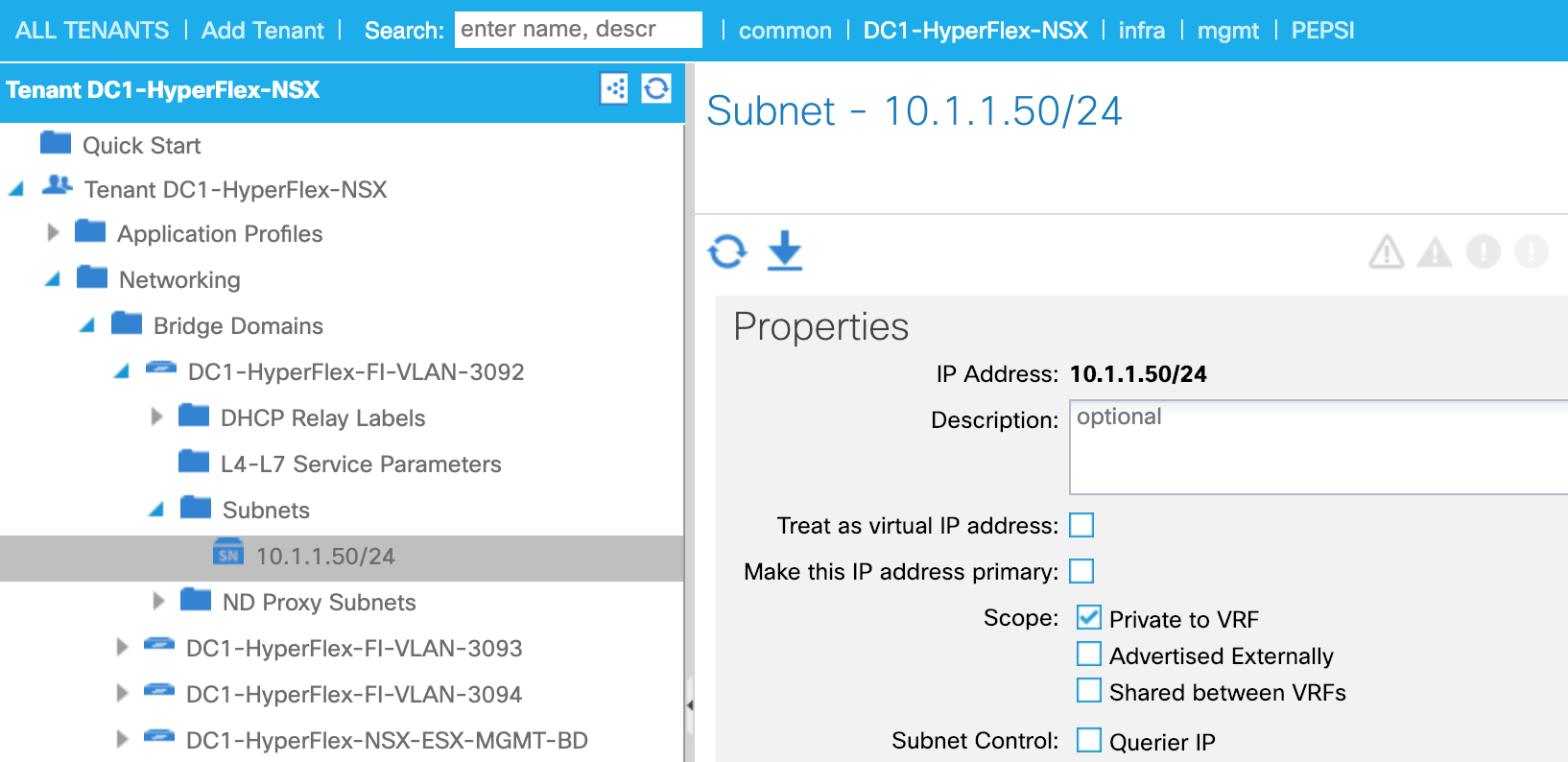
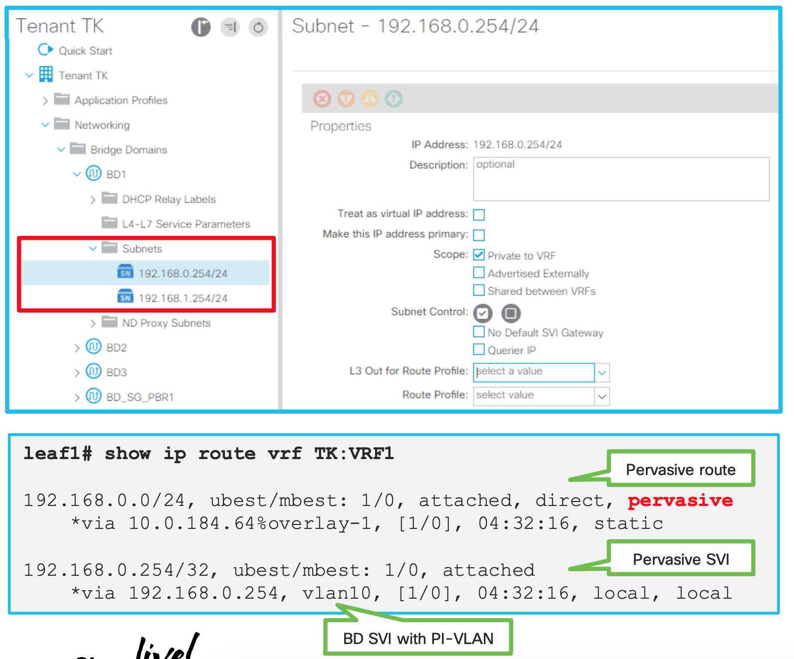
How is pervasive GW deployed? (When no contracts associated)
-
PI-VLAN for BD is used to represent a pervasive GW SVI
-
A pervasive SVI has secondary IP when multiple pervasive GWs are configured on the same BD
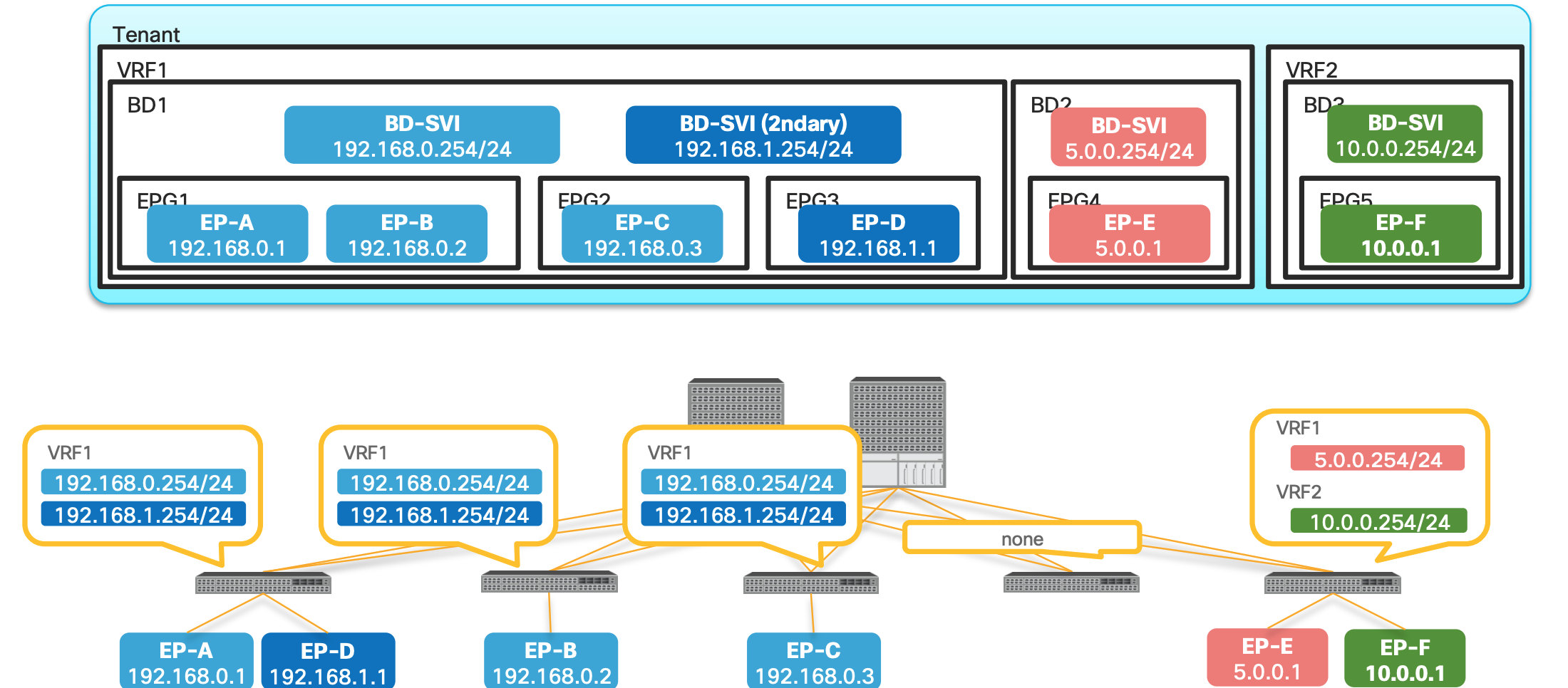
- In the above picture Bridge Domain has multiple EPGs in it.
- Both Primary and Secondary SVIs are installed on the switches which has EPGs or Endpoints assigned on those leafs.
- Leaf 4 does not have any EPs , hence no SVIs
- EP-E and EP-F are only on 5th Leaf hence the SVIs are only there.
How is pervasive GW deployed? (When a contract is associated)
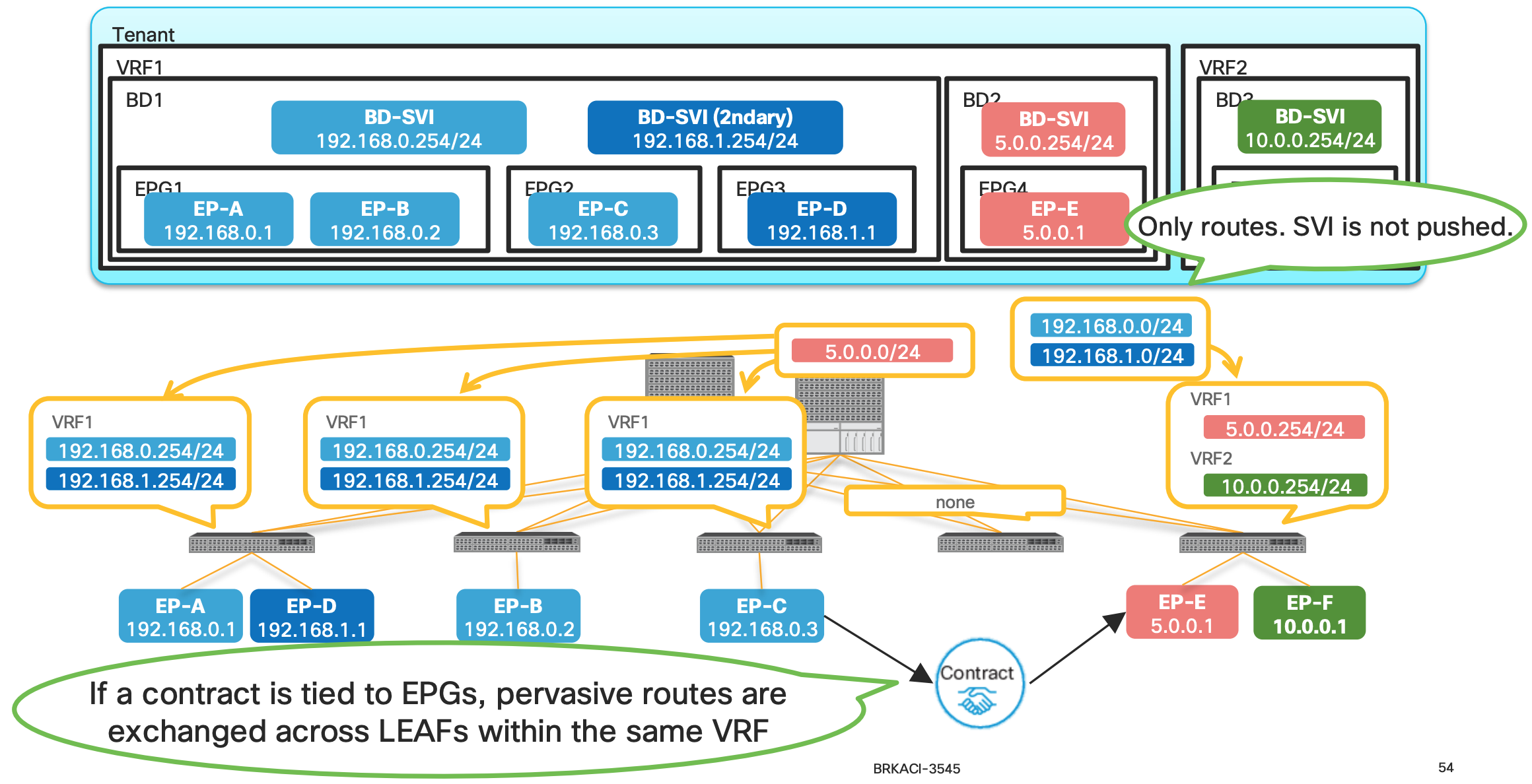
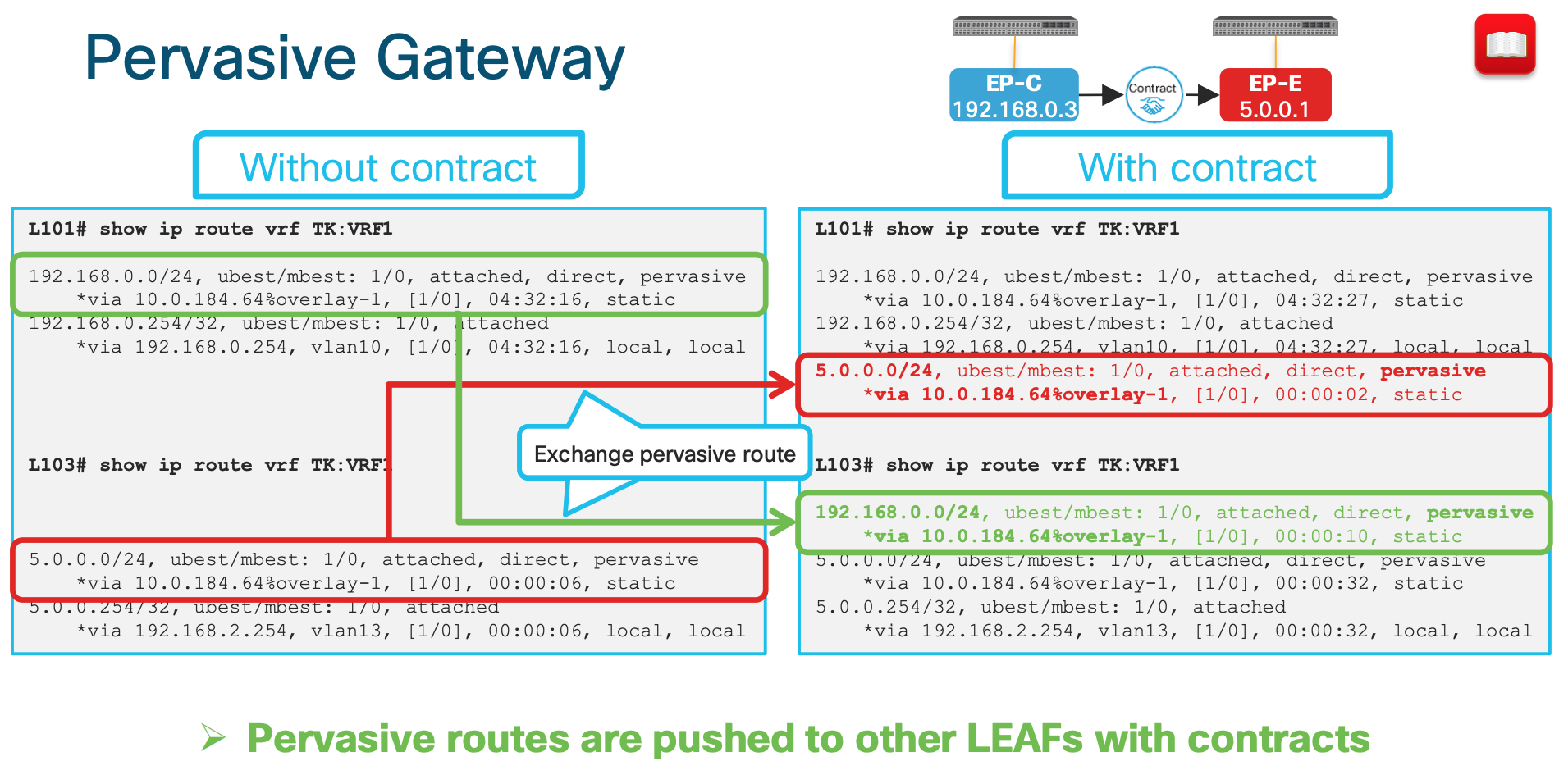
- When a contract is associated , the pervasive routes are exchanged.
- In the above example since the contract are between Endpoint-C and Endpoint-E the Pervasive routes of the Bridge Domain are exchanged between the BD1 and BD2.
- In this example , the pervasive route
5.0.0.254is shared to the BD1 and same from BD1 (192.168.0.254 and 192.168.1.254) is shared to the BD2.
Why are we doing the above exchange of routes ?
This is the key to understand how the ACI is doing Spine-Proxy Why does ACI push pervasive routes to other LEAFs after a contract? Pervasive routes are required for Spine-Proxy
Let’s understand it better :
What is a Spine Proxy
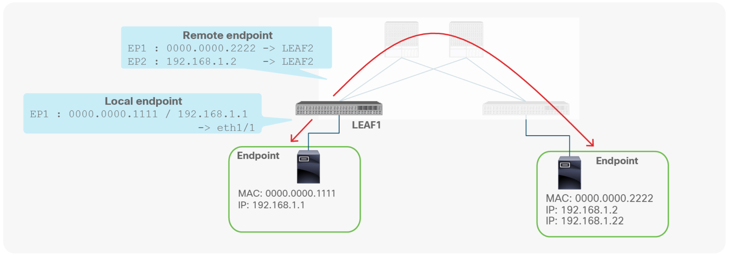
A leaf switch has two types of endpoints: local endpoints and remote endpoints. Local endpoints for LEAF1 reside directly on LEAF1 (For example, directly attached), whereas remote endpoints for LEAF1 reside on other leaf endpoints (picture above).
Although both local and remote endpoints are learned from the data plane, remote endpoints are merely a cache, local to each leaf. Local endpoints are the main source of endpoint information for the entire Cisco ACI fabric. Each leaf is responsible for reporting its local endpoints to the Council Of Oracle Protocol (COOP) database, located on each spine switch, which implies that all endpoint information in the Cisco ACI fabric is stored in the spine COOP database. Because this database is accessible, each leaf does not need to know about all the remote endpoints to forward packets to the remote leaf endpoints. Instead, a leaf can forward packets to spine switches, even if the leaf does not know about a particular remote endpoint. This forwarding behavior is called S P I N E - P R O X Y.
Now coming back to the question of Why does ACI push pervasive routes to other LEAFs after a contract?
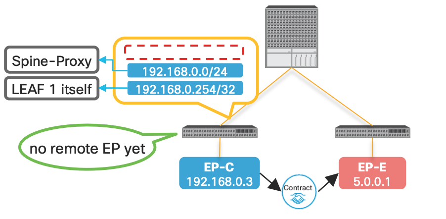
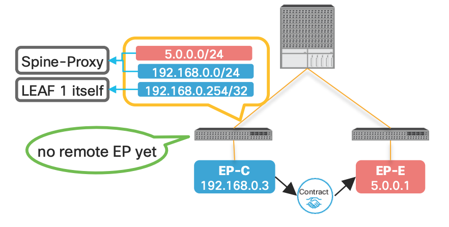
###Without the pervasive route:
| WITHOUT Pervasive Route | WITH Pervasive Route |
|---|---|
| In the below example since there is no pervasive route the communication will not happen with EP-E from EP-C | In this case with the SPINE Proxy route EP-C can send the traffice to SPINE since it knows the path is via SPINE |
 |
 |
This is what the outputs looks like in CLI when the contract is applied:
ACI Forwarding Scope Concepts
This is one of the best slides showing the communication scenarios and whether its switched or routed. Look at the detailed explanation below:
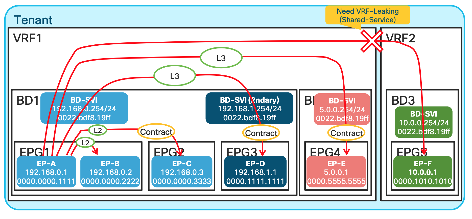
EP-A talking to EP-B: In this scenario , since both EPGs are in the same subnet and same L2 domain the traffic is Layer 2 Switched.EP-A talking to EP-C: Same Bridge domain but differen EPG , and has a contract , still L2 switched.EP-A talking to EP-D: Same BD , but different subnet ; hence L3 routed.EP-A talking to EP-E: Different BD and different network hence L3 switched.EP-A talking to EP-F: Differen VRF , unless route leaking is implemented no traffic communication happens.
ACI Lab Use Cases Walk Through
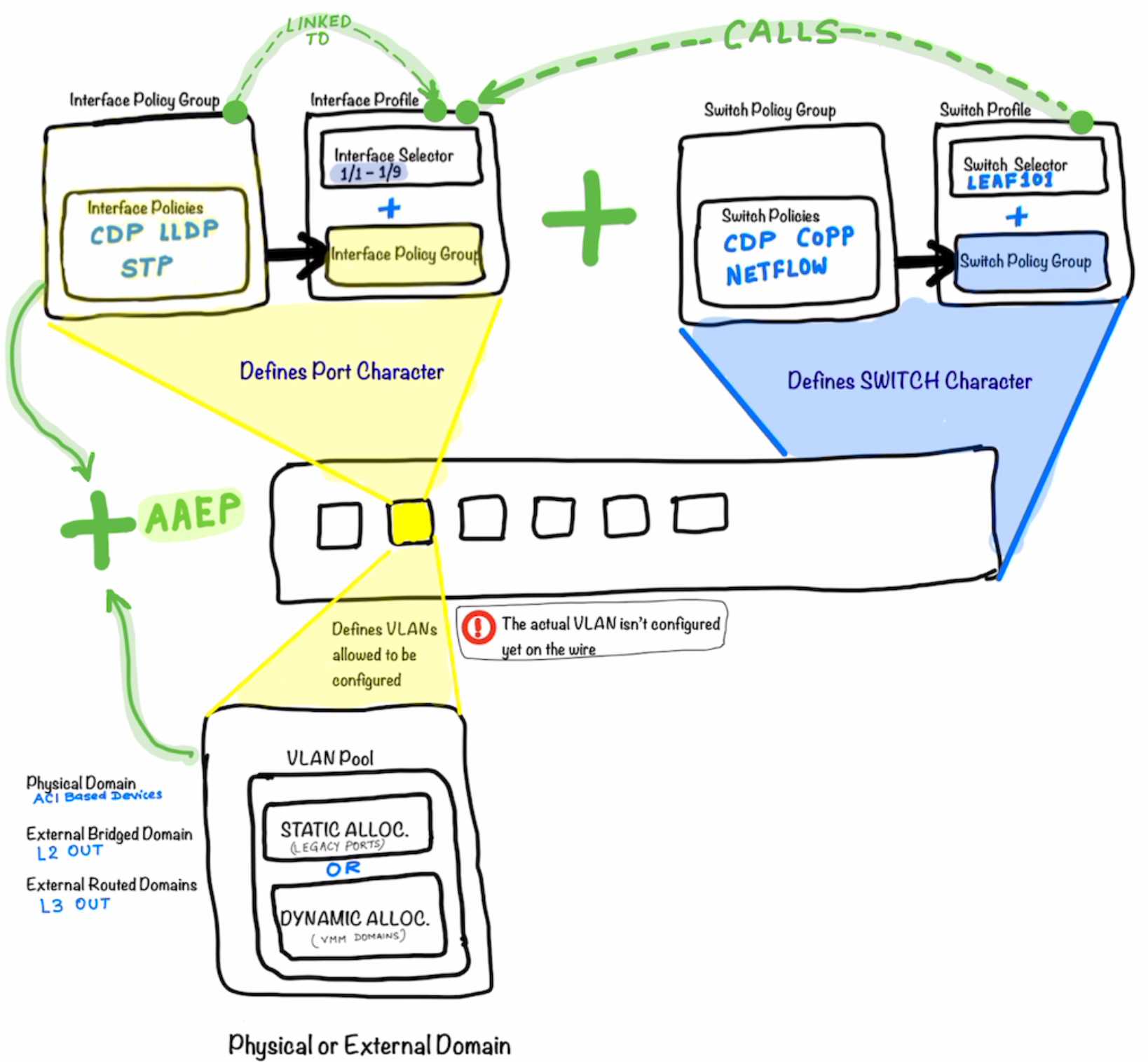
The following diagram illustrates what make a ACI Switch defined. Just like in UCS we define the Service Profile; In the Profile creating with ACI; the Interface Profile defines the characteristics of the Interfaces while the Switch Profile defines the characteristics of the Switch itself .
Joining the Interface Profile and Switch Profile together makes the whole Switch .
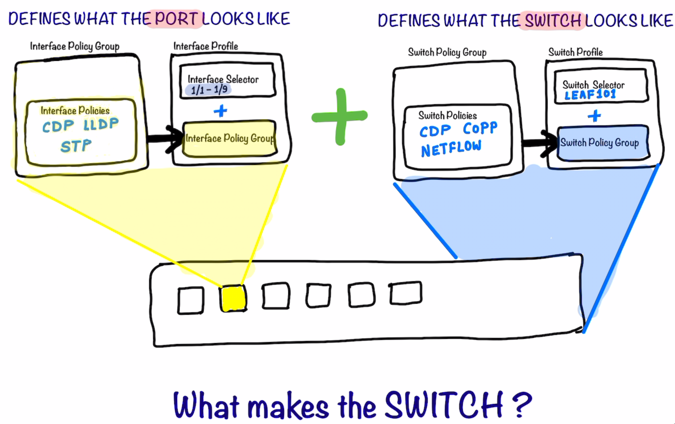
After the step above ; as a next step we start defining what are the VLANs that could be allowed on the port. Remember that these VLANs still are not assigned to the port. They are just the vlans which are being allowed to be configured/used on the port.
-
The Physical Domain is for ACI Based devices (Devices Residing on ACI)
- External Bridge Domain is for L2Out
- External Routed Domain is for L3Out
The External Domain and the allowed VLANs are now added to the Port Profile using AAEP ; which ties them together.
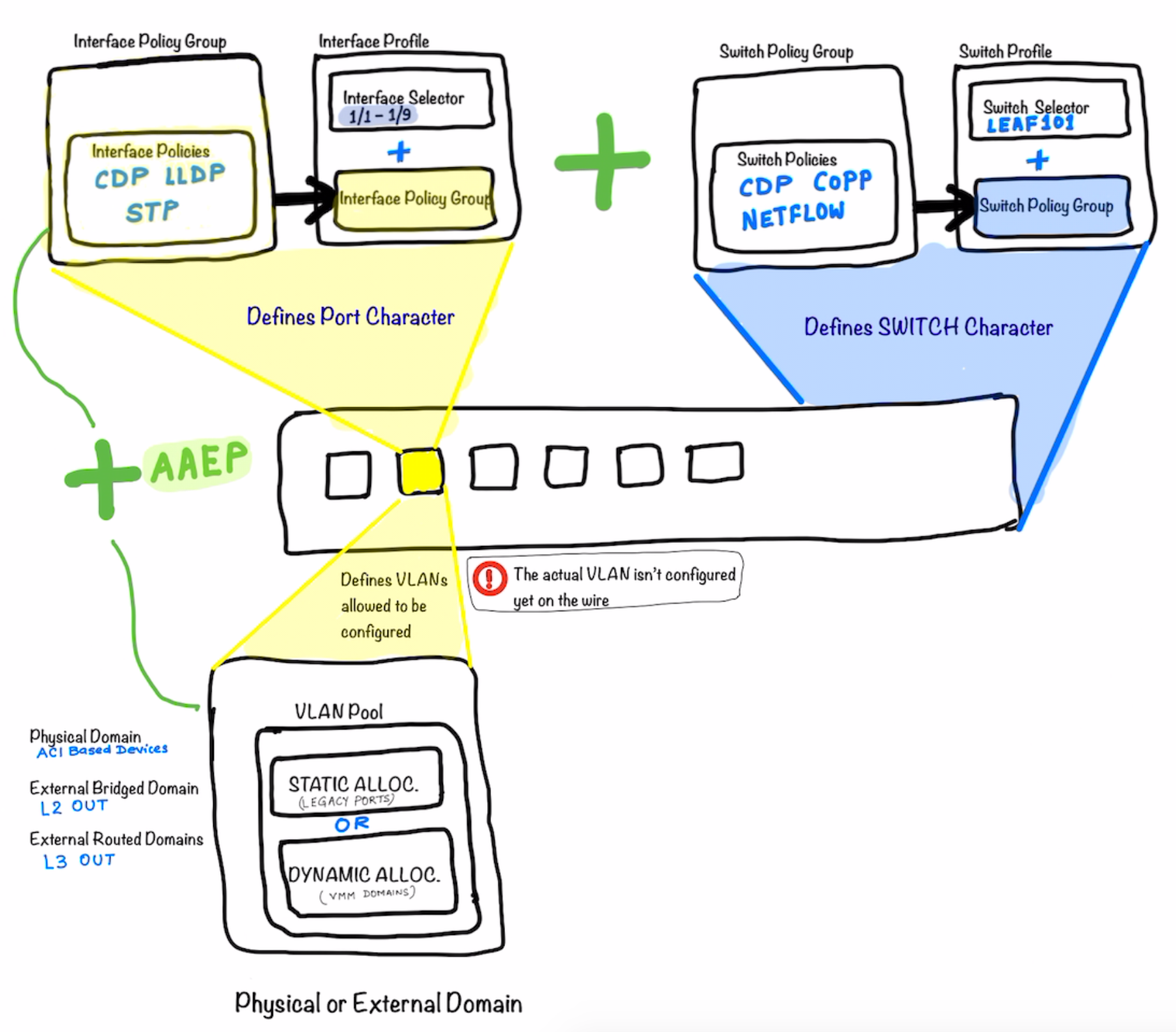
The picture below illustrates what’s explained above in more details. Look at how the different components are called and tied to each other .
The Switch Policy Group is tied to the Switch Profile which in turn is called-in in the Interface Profile .
The Interface Profile is then tied to the Interface Policy Group
Definitions of the Interface Policy Groups are key part of the ACI Configuration **Notice that in the top half of the picture the main components is the the
Interface Policy Group**
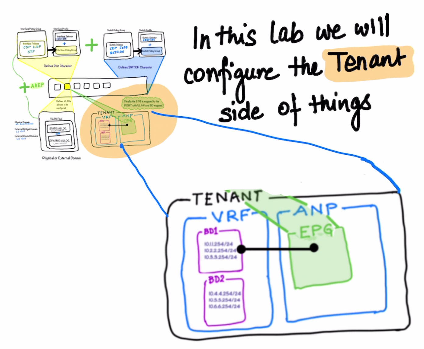
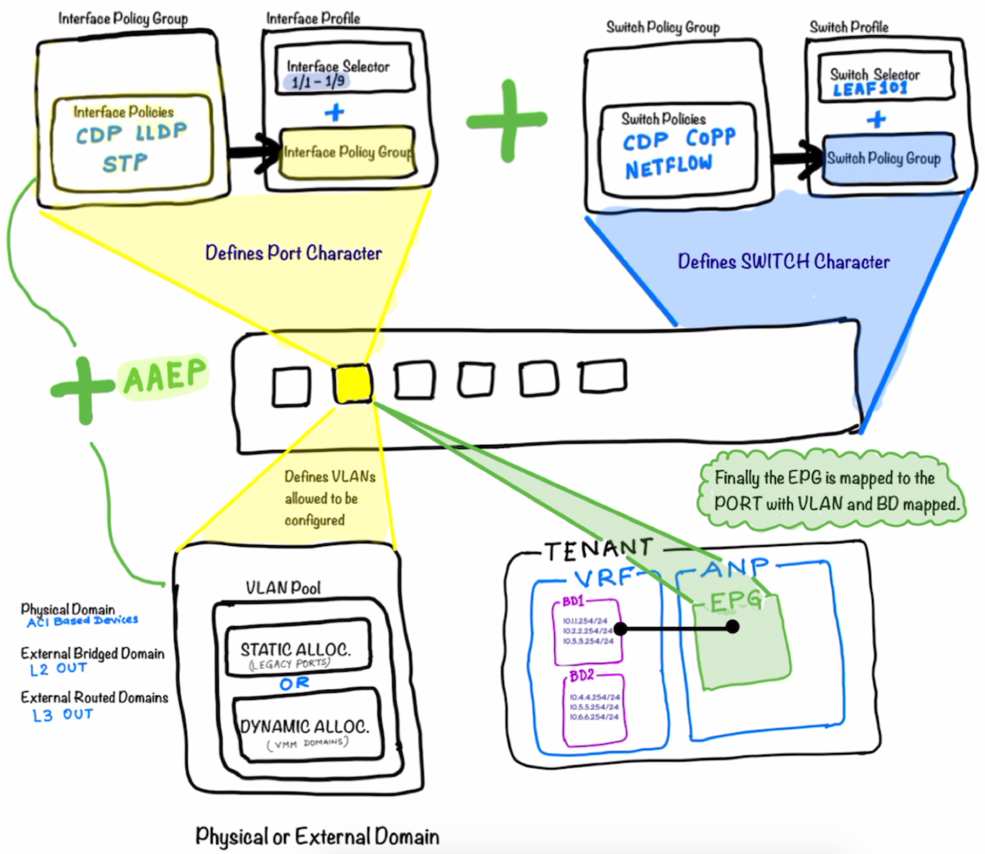
Now as a next step of progressing on the workflow above ; we create the Tenant under which the EPG is created and tied to the port which is the actual networking construct in ACI and completes the whole picture .
The picture illustrates that the Tenant is created ; under which the VRF and the Bridge Domains are created.
After that the Application Network Profile is created under which the EPG is defined.
This EPG is in the end tied to the the Bridge Domain completing the whole workflow.
Notice that there is no explicit mapping between the Switch Profile / Interface Profile configs and the Tenant Config (EPG) ; so do not confuse
What we cover
- Basic Setup [Fabric Setup]
- Tenant Setup [Tenant , VRF , Bridge Domain , Subnets]
- Creation of the EPGs
- Contracts
- L2OUT using standard port channel
- L2Out using VPC
- EPGs for L2 Out
- L3 Out Using OSPF
- EPGs for L3 Outs
- L3 Out for EIGRP
- Transit Routing
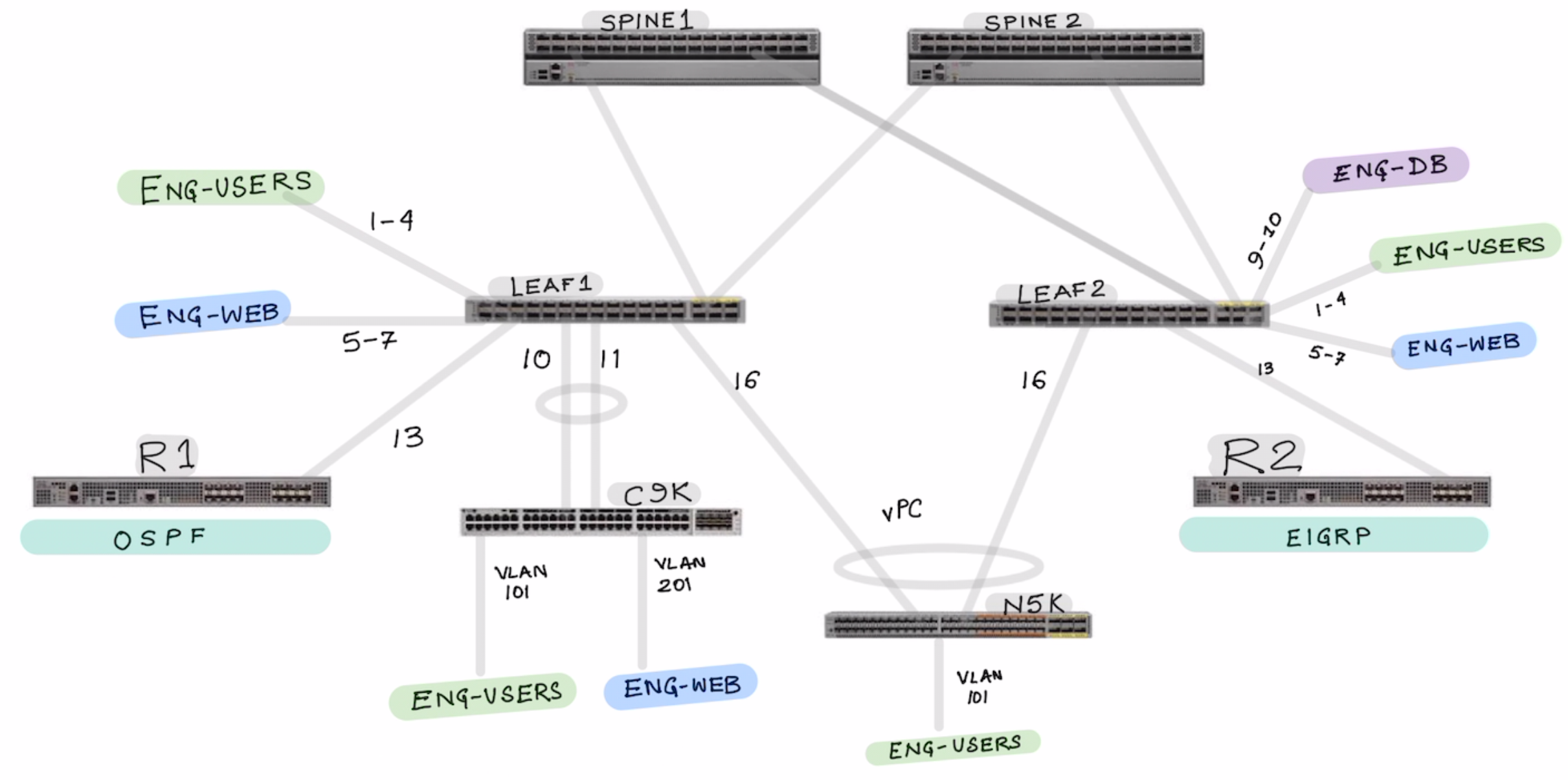
In the above topology we configure the following topics:
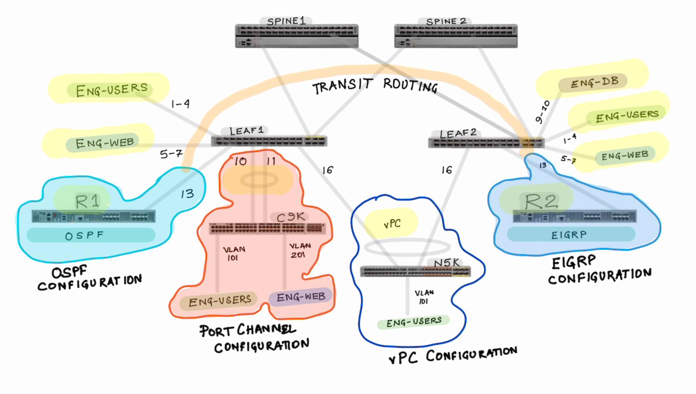
Part 1: Interface Policy Group and Interface Profile Configuration
Lets start by configuring the Interface Policy Group and Interface Profile
- IPG-ENG-USERS
- IPG-ENG-WEB-SERVERS
- IPG-ENG-DB-SERVERS
- IPG-ROUTER-1-OSPF
- IPG-ROUTER-2-EIGRP
Notice how the port channels are differently created for Regular Port Channel and vPC based port-channel.
- IPG-PORT-CHANNEL-REGULAR
- IPG-VPC-PORT-CHANNEL-LEAF1-LEAF2
Show where you see the port-channels once they are created.
Now Lets configure the Interface Profiles
- Create the Interface Profile for Each Switches SW1-INT-PROFILE SW2-INT-PROFILE
Notice in the picture below , the interface profile is switch specific . It makes sense so that It can be tied to a specific switch profile.
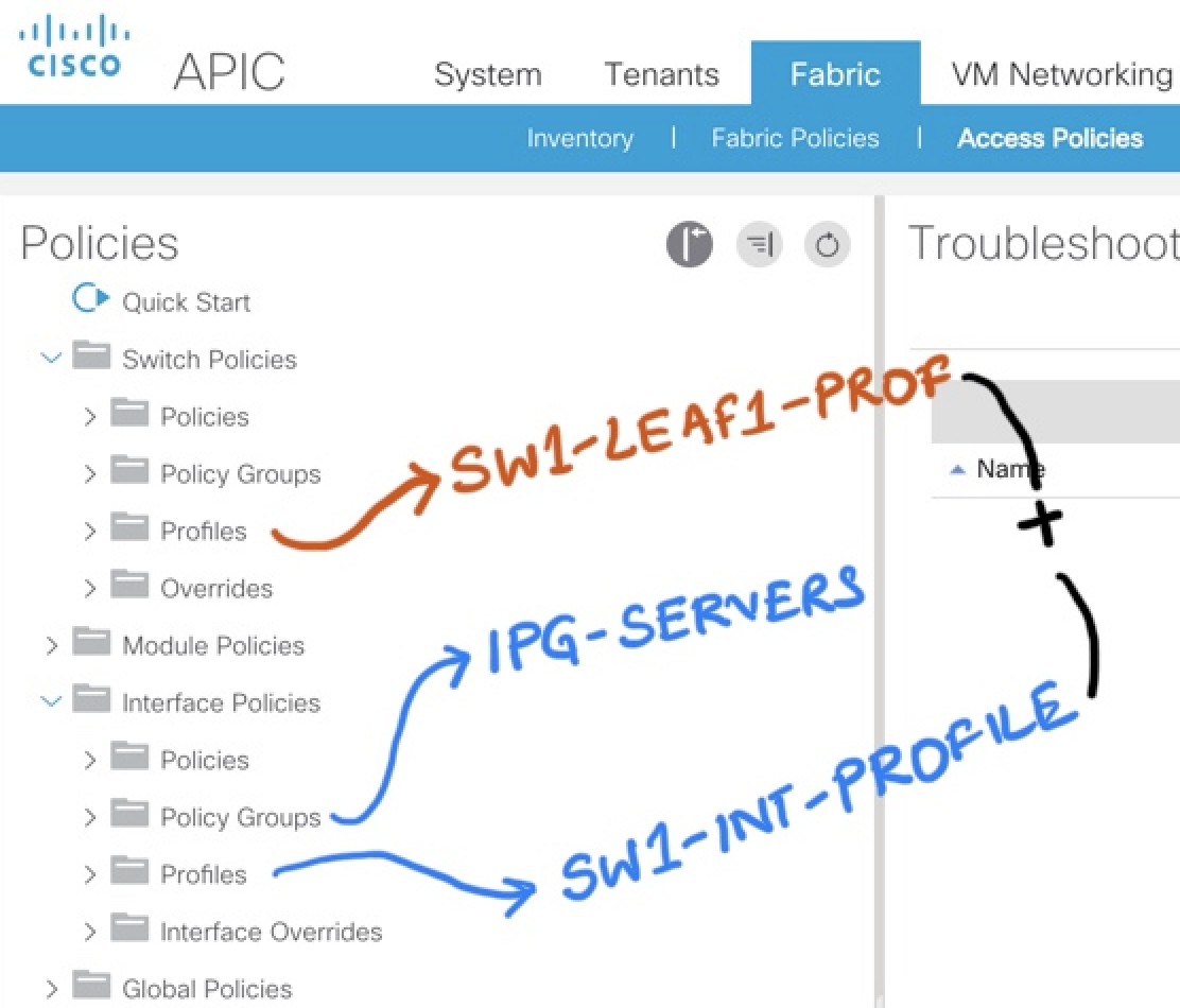
VIDEO HERE OF THE ABOVE INTEFACE CONFIGURATIONS
Part 2: Switch Policy Group and Switch Profile Configuration
How to configure VPC and Map the interface configuration .
Subscribe via RSS
